
1. OptaPlanner Engine
See the OptaPlanner User Guide.
OptaPlanner Workbench
2. Quickstart
2.1. Cloud Balancing Example Setup
This chapter describes the process of setting up environment to run Cloud Balancing example using KIE Workbench and KIE Server. At the end of the chapter, the user will be able to submit sample planning problem to the KIE Server and query the best solution.
2.1.1. Environment Setup
The first step consists of setting up Wildfly instance and deploying KIE artifacts.
2.1.1.1. Download Required Artifacts:
-
Java EE compliant application server. This example uses WildFly
-
KIE Server and KIE Workbench war files from OptaPlanner website
2.1.1.2. Create New User
-
Unix users:
$WILDFLY_HOME/bin/add-user.sh -
Windows users:
$WILDFLY_HOME/bin/add-user.bat-
User type: application user
-
Username: planner
-
Password: Planner123_
-
Groups: kie-server,admin
-
2.1.1.3. Deploy KIE Workbench & KIE Server
-
Copy KIE Workbench war to
$WILDFLY_HOME/standalone/deployments/kie-wb.war -
Copy KIE Server war to
$WILDFLY_HOME/standalone/deployments/kie-server.war
2.1.1.4. Start Server
-
Unix users:
./bin/standalone.sh --server-config=standalone-full.xml \ -Dorg.kie.server.user=planner \ -Dorg.kie.server.pwd=Planner123_ \ -Dorg.kie.server.controller.user=planner \ -Dorg.kie.server.controller.pwd=Planner123_ \ -Dorg.kie.server.id=wildfly-kieserver \ -Dorg.kie.server.location=http://localhost:8080/kie-server/services/rest/server \ -Dorg.kie.server.controller=http://localhost:8080/kie-wb/rest/controller -
Windows users:
./bin/standalone.bat --server-config=standalone-full.xml \
 -Dorg.kie.server.user=planner \
 -Dorg.kie.server.pwd=Planner123_ \
 -Dorg.kie.server.controller.user=planner \
 -Dorg.kie.server.controller.pwd=Planner123_ \
 -Dorg.kie.server.id=wildfly-kieserver \
 -Dorg.kie.server.location=http://localhost:8080/kie-server/services/rest/server \
 -Dorg.kie.server.controller=http://localhost:8080/kie-wb/rest/controller
2.1.1.5. Open the Workbench in Browser
Navigate to http://localhost:8080/kie-wb in a web browser to access the Workbench. Use credentials defined in the previous step to log in.
2.1.2. Project Setup
The second step consists of setting up logical structures required to create a new project.
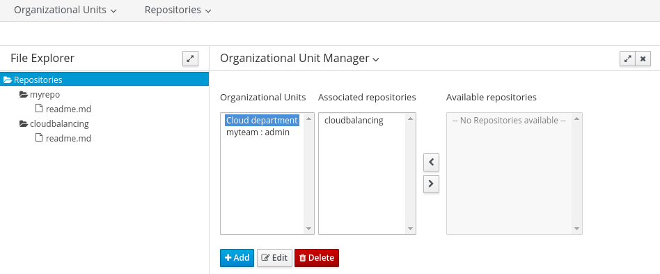
2.1.2.1. Create Organizational Unit
-
Navigate to Authoring → Administration → Organizational Units → Manage Organizational Units and click Add
-
Name: Cloud department
-
Default Group ID: clouddepartment
-
2.1.2.2. Create Repository
-
Select Authoring → Administration → Repositories → New repository
-
Repository Name: cloudbalancing
-
In Organizational Unit: Cloud department
-
2.1.2.3. Create Project
-
Select Authoring → Project Authoring → New Project → Advanced setup
-
Project Name: cloudbalancing
-
Project Description: Assign processes to computers based on available CPU power, memory, network bandwidth and cost
-
Group ID: clouddepartment
-
Artifact ID: cloudbalancing
-
Version: 1.0
-
2.1.3. Data Model
This step consists of creating data model for the Cloud Balancing problem. Data objects and their attributes are defined.
2.1.3.1. Create Data Object
-
Select Create New Asset → Data Object
-
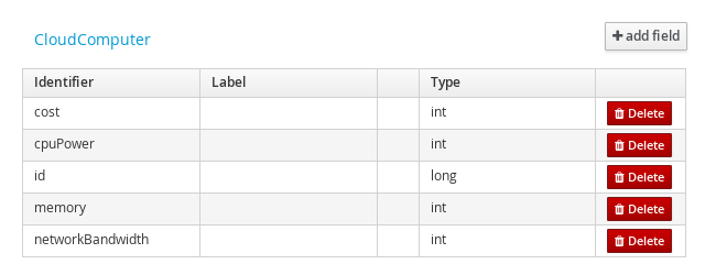
Data Object: CloudComputer
-
Package: clouddepartment.cloudbalancing
-
2.1.3.2. Add Fields
Add multiple fields of given types.
-
Click Add field
-
id: long
-
cpuPower: int
-
memory: int
-
networkBandwith: int
-
cost: int
-
-
Click Save
-
Click Close icon
2.1.3.3. Complete the Data Model
Using the same approach, create CloudProcess and CloudBalance data objects with the following attributes:
-
CloudProcess
-
id: long
-
requiredCpuPower: int
-
requiredMemory: int
-
requiredNetworkBandwith: int
-
computer: clouddepartment.cloudbalancing.CloudComputer
-
-
CloudBalance
-
id: long
-
computerList: List<clouddepartment.cloudbalancing.CloudComputer>
-
processList: List<clouddepartment.cloudbalancing.CloudProcess>
-
2.1.4. Planner Configuration
This section explains how to enhance the data model created in the previous step with Planner annotations.
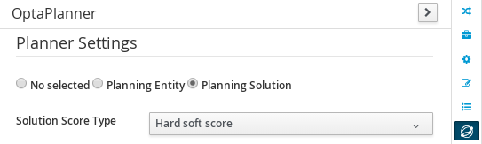
2.1.4.1. CloudBalance Data Object
-
Select CloudBalance
-
Open OptaPlanner dock
-
Check Planning Solution
-
-
Select computerList field
-
Open OptaPlanner dock
-
Check Planning Value Range Provider
-
Set id to
computerRange
-
-
Select processList field
-
Open OptaPlanner dock
-
Check Planning Entity Collection
-
-
Click Save
-
Click Close icon
2.1.4.2. CloudProcess
-
Select CloudProcess
-
Open OptaPlanner dock
-
Check Planning Entity
-
-
Select computer field
-
Open OptaPlanner dock
-
Check Planning Variable
-
Set valueRangeId to
computerRange
-
-
Click Save
-
Click Close icon
2.1.5. Drools Rules
This section contains constraint definitions for the CloudBalancing problem using two different approaches - Free-form DRL Editor and Guided Rule Editor.
2.1.5.1. Free-form DRL Editor
-
Select Create New Asset → DRL file
-
DRL file: cloudBalancingScoreRules
-
Package: clouddepartment.cloudbalancing
package clouddepartment.cloudbalancing;

import org.optaplanner.core.api.score.buildin.hardsoft.HardSoftScoreHolder;

import clouddepartment.cloudbalancing.CloudBalance;
import clouddepartment.cloudbalancing.CloudComputer;
import clouddepartment.cloudbalancing.CloudProcess;

rule "requiredCpuPowerTotal"
    when
        $computer : CloudComputer($cpuPower : cpuPower)
        accumulate(
            CloudProcess(
                computer == $computer,
                $requiredCpuPower : requiredCpuPower);
            $requiredCpuPowerTotal : sum($requiredCpuPower);
            $requiredCpuPowerTotal > $cpuPower
        )
    then
        scoreHolder.addHardConstraintMatch(kcontext, $cpuPower - $requiredCpuPowerTotal);
end

rule "requiredMemoryTotal"
    when
        $computer : CloudComputer($memory : memory)
        accumulate(
            CloudProcess(
                computer == $computer,
                $requiredMemory : requiredMemory);
            $requiredMemoryTotal : sum($requiredMemory);
            $requiredMemoryTotal > $memory
        )
    then
        scoreHolder.addHardConstraintMatch(kcontext, $memory - $requiredMemoryTotal);
end

rule "requiredNetworkBandwidthTotal"
    when
        $computer : CloudComputer($networkBandwidth : networkBandwidth)
        accumulate(
            CloudProcess(
                computer == $computer,
                $requiredNetworkBandwidth : requiredNetworkBandwidth);
            $requiredNetworkBandwidthTotal : sum($requiredNetworkBandwidth);
            $requiredNetworkBandwidthTotal > $networkBandwidth
        )
    then
        scoreHolder.addHardConstraintMatch(kcontext, $networkBandwidth - $requiredNetworkBandwidthTotal);
end
-
-
Click Save
-
Click Close icon
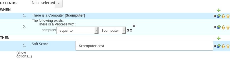
2.1.5.2. Guided Rule Editor
-
Select Create New Asset → Guided Rule
-
Guided Rule: computerCost
-
Package: clouddepartment.cloudbalancing
-
-
Click Save
-
Click Close icon
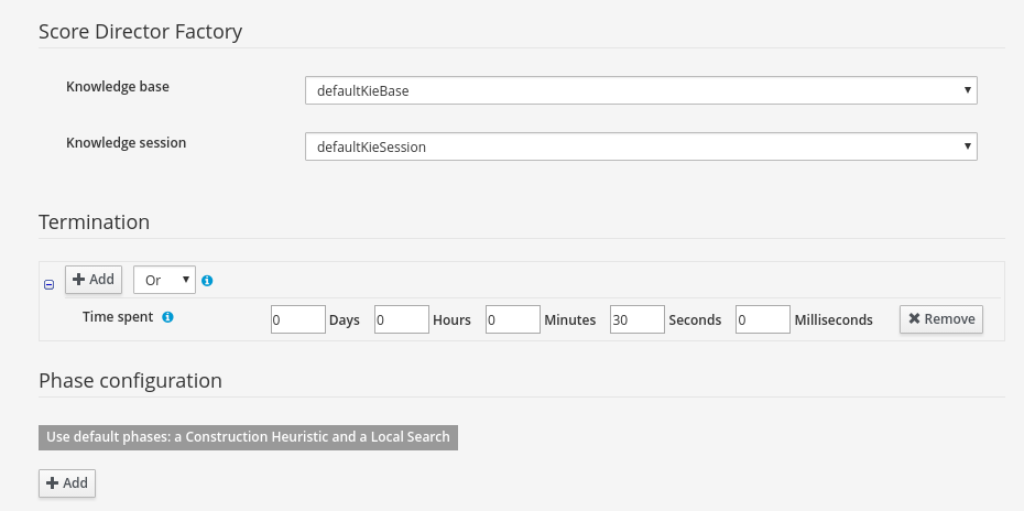
2.1.6. Solver Configuration
The following task is to create Planner Solver configuration to tweak engine parameters.
2.1.6.1. Create Solver Configuration
-
Select Create New Asset → Solver configuration
-
Solver configuration: Cloud Balancing Solver Configuration
-
Package: clouddepartment.cloudbalancing
-
Navigate to Termination
-
Click Add and select Time spent
-
Set Seconds to
30to stop the solving process after 30 seconds
-
-
-
Click Save
-
Click Close icon
2.1.7. Build & Deploy
2.1.7.1. Add Kie Container
-
Navigate to Deploy → Execution Servers and click Add Container
-
Name: cloudbalancing
-
Group Name: clouddepartment
-
Artifact Id: cloudbalancing
-
Version: 1.0
-
2.1.7.2. Build Project
-
Navigate to Authoring → Project Authoring → cloudbalancing and click Build & Deploy
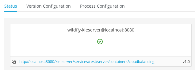
2.1.7.3. Start Container
-
Navigate to Deploy → Execution Servers
-
Select container cloudbalancing and click Start
-
2.1.8. KIE Server Integration
This section describes basic steps required to set up Planner & KIE Server integration. A sample Cloud Balancing problem instance is submitted to the KIE Server and the result is queried using REST API the server exposes.
All HTTP requests performed in this chapter use the following header:
authorization: Basic cGxhbm5lcjpQbGFubmVyMTIzXw==
X-KIE-ContentType: xstream
content-type: application/xml
2.1.8.1. Register Solver
-
Request body
<solver-instance>
  <solver-config-file>clouddepartment/cloudbalancing/Cloud Balancing Solver Configuration.solver.xml</solver-config-file>
</solver-instance>
2.1.8.2. Submit Solution
-
Request body
<planning-problem class="clouddepartment.cloudbalancing.CloudBalance" id="1">
  <id>0</id>
  <computerList id="2">
    <clouddepartment.cloudbalancing.CloudComputer id="3">
      <id>0</id>
      <cpuPower>24</cpuPower>
      <memory>96</memory>
      <networkBandwidth>16</networkBandwidth>
      <cost>4800</cost>
    </clouddepartment.cloudbalancing.CloudComputer>
    <clouddepartment.cloudbalancing.CloudComputer id="4">
      <id>1</id>
      <cpuPower>6</cpuPower>
      <memory>4</memory>
      <networkBandwidth>6</networkBandwidth>
      <cost>660</cost>
    </clouddepartment.cloudbalancing.CloudComputer>
  </computerList>
  <processList id="5">
    <clouddepartment.cloudbalancing.CloudProcess id="6">
      <id>0</id>
      <requiredCpuPower>1</requiredCpuPower>
      <requiredMemory>1</requiredMemory>
      <requiredNetworkBandwidth>1</requiredNetworkBandwidth>
    </clouddepartment.cloudbalancing.CloudProcess>
    <clouddepartment.cloudbalancing.CloudProcess id="7">
      <id>1</id>
      <requiredCpuPower>3</requiredCpuPower>
      <requiredMemory>6</requiredMemory>
      <requiredNetworkBandwidth>1</requiredNetworkBandwidth>
    </clouddepartment.cloudbalancing.CloudProcess>
    <clouddepartment.cloudbalancing.CloudProcess id="8">
      <id>2</id>
      <requiredCpuPower>1</requiredCpuPower>
      <requiredMemory>1</requiredMemory>
      <requiredNetworkBandwidth>3</requiredNetworkBandwidth>
    </clouddepartment.cloudbalancing.CloudProcess>
    <clouddepartment.cloudbalancing.CloudProcess id="9">
      <id>3</id>
      <requiredCpuPower>1</requiredCpuPower>
      <requiredMemory>2</requiredMemory>
      <requiredNetworkBandwidth>11</requiredNetworkBandwidth>
    </clouddepartment.cloudbalancing.CloudProcess>
    <clouddepartment.cloudbalancing.CloudProcess id="10">
      <id>4</id>
      <requiredCpuPower>1</requiredCpuPower>
      <requiredMemory>1</requiredMemory>
      <requiredNetworkBandwidth>1</requiredNetworkBandwidth>
    </clouddepartment.cloudbalancing.CloudProcess>
    <clouddepartment.cloudbalancing.CloudProcess id="11">
      <id>5</id>
      <requiredCpuPower>1</requiredCpuPower>
      <requiredMemory>1</requiredMemory>
      <requiredNetworkBandwidth>5</requiredNetworkBandwidth>
    </clouddepartment.cloudbalancing.CloudProcess>
  </processList>
</planning-problem>
2.1.8.3. Query Best Solution
-
-
Verify that the
computerattributes ofCloudProcessinstances are assigned
-
3. Workbench (General)
3.1. Installation
3.1.1. War installation
Use the war from the workbench distribution zip that corresponds to your application server.
The differences between these war files are mainly superficial.
For example, some JARs might be excluded if the application server already supplies them.
-
eap7: tailored for Red Hat JBoss Enterprise Application Platform 7 -
tomcat8: tailored for Apache Tomcat 8Apache Tomcat requires additional configuration to correctly install the Workbench. Please consult the
README.mdin thewarfor the most up to date procedure. -
wildfly10: tailored for Red Hat JBoss Wildfly 10
3.1.2. Workbench data
The workbench stores its data, by default in the directory $WORKING_DIRECTORY/.niogit, for example wildfly-10.0.0.Final/bin/.niogit, but it can be overridden with the system property-Dorg.uberfire.nio.git.dir.
|
In production, make sure to back up the workbench data directory. |
3.1.3. System properties
Here’s a list of all system properties:
-
org.uberfire.nio.git.dir: Location of the directory.niogit. Default: working directory -
org.uberfire.nio.git.dirname: Name of the git directory. Default:.niogit -
org.uberfire.nio.git.daemon.enabled: Enables/disables git daemon. Default:true -
org.uberfire.nio.git.daemon.host: If git daemon enabled, uses this property as local host identifier. Default:localhost -
org.uberfire.nio.git.daemon.port: If git daemon enabled, uses this property as port number. Default:9418 -
org.uberfire.nio.git.ssh.enabled: Enables/disables ssh daemon. Default:true -
org.uberfire.nio.git.ssh.host: If ssh daemon enabled, uses this property as local host identifier. Default:localhost -
org.uberfire.nio.git.ssh.port: If ssh daemon enabled, uses this property as port number. Default:8001 -
org.uberfire.nio.git.ssh.cert.dir: Location of the directory.securitywhere local certificates will be stored. Default: working directory -
org.uberfire.nio.git.ssh.passphrase: Passphrase to access your Operating Systems public keystore when cloninggitrepositories withscpstyle URLs; e.g.git@github.com:user/repository.git. -
org.uberfire.nio.git.ssh.algorithm: Algorithm used by SSH. Default:DSAIf you plan to use RSA or any algorithm other than DSA, make sure you setup properly your Application Server to use Bouncy Castle JCE library.
-
org.uberfire.metadata.index.dir: Place where Lucene.indexfolder will be stored. Default: working directory -
org.uberfire.cluster.id: Name of the helix cluster, for example:kie-cluster -
org.uberfire.cluster.zk: Connection string to zookeeper. This is of the formhost1:port1,host2:port2,host3:port3, for example:localhost:2188 -
org.uberfire.cluster.local.id: Unique id of the helix cluster node, note that ‘`:`’ is replaced with ‘`\_`’, for example:node1_12345 -
org.uberfire.cluster.vfs.lock: Name of the resource defined on helix cluster, for example:kie-vfs -
org.uberfire.cluster.autostart: Delays VFS clustering until the application is fully initialized to avoid conflicts when all cluster members create local clones. Default:false -
org.uberfire.ldap.regex.role_mapper: Regex pattern used to map LDAP principal names to application role name. Note that the variablerolemust be part of the pattern as it is substited by the application role name when matching a principal value to role name. Default: Not used. -
org.uberfire.sys.repo.monitor.disabled: Disable configuration monitor (do not disable unless you know what you’re doing). Default:false -
org.uberfire.secure.key: Secret password used by password encryption. Default:org.uberfire.admin -
org.uberfire.secure.alg: Crypto algorithm used by password encryption. Default:PBEWithMD5AndDES -
org.uberfire.domain: security-domain name used by uberfire. Default:ApplicationRealm -
org.guvnor.m2repo.dir: Place where Maven repository folder will be stored. Default: working-directory/repositories/kie -
org.guvnor.project.gav.check.disabled: Disable GAV checks. Default:false -
org.kie.example.repositories: Folder from where demo repositories will be cloned. The demo repositories need to have been obtained and placed in this folder. Demo repositories can be obtained from the kie-wb-6.2.0-SNAPSHOT-example-repositories.zip artifact. This System Property takes precedence over org.kie.demo and org.kie.example. Default: Not used. -
org.kie.demo: Enables external clone of a demo application from GitHub. This System Property takes precedence over org.kie.example. Default:true -
org.kie.example: Enables example structure composed by Repository, Organization Unit and Project. Default:false -
org.kie.build.disable-project-explorer: Disable automatic build of selected Project in Project Explorer. Default:false -
org.kie.verification.disable-dtable-realtime-verification: Disables the realtime validation and verification of decision tables. Default:false
To change one of these system properties in a WildFly or JBoss EAP cluster:
-
Edit the file
$JBOSS_HOME/domain/configuration/host.xml. -
Locate the XML elements
serverthat belong to themain-server-groupand add a system property, for example:<system-properties> <property name="org.uberfire.nio.git.dir" value="..." boot-time="false"/> ... </system-properties>
3.1.4. Trouble shooting
3.1.4.1. Loading.. does not disappear and Workbench fails to show
There have been reports that Firewalls in between the server and the browser can interfere with Server Sent Events (SSE) used by the Workbench.
The issue results in the "Loading…" spinner remaining visible and the Workbench failing to materialize.
The workaround is to disable the Workbench’s use of Server Sent Events by adding file /WEB-INF/classes/ErraiService.properties to the exploded WAR containing the value errai.bus.enable_sse_support=false.
Re-package the WAR and re-deploy.
Some Users have also reported disabling Server Sent Events does not resolve the issue. The solution found to work is to configure the JVM to use a different Entropy Gathering Device on Linux for SecureRandom. This can be configured by setting System Property java.security.egd to file:/dev/./urandom. See this Stack Overflow post for details.
Please note however this affects the JVM’s random number generation and may present other challenges where strong cryptography is required. Configure with caution.
3.1.4.2. Not able to clone KIE Workbench Git repository using ssh protocol.
Git clients using ssh to interact with the Git server that is bundled with Workbench are authenticated and authorized to perform git commands by the security API that is part of the Uberfire backend server. When using an LDAP security realm, some git clients were not being authorized as expected. This was due to the fact that for non-web clients such as Git via ssh, the principal (i.e., user or group) name assigned to a user by the application server’s user registry is the more complex DN associated to that principal by LDAP. The logic of the Uberfire backend server looked for on exact match of roles allowed with the principal name returned and therefore failed.
It is now possible to control the role-principal matching via the system property
org.uberfire.ldap.regex.role_mapperwhich takes as its value a Regex pattern to be applied when matching LDAP principal to role names. The pattern must contain the literal word variable 'role'. During authorization the variable is replaced by each of the allow application roles. If the pattern is matched the role is added to the user.
For instance, if the DN for the admin group in LDAP is
DN: cn=admin,ou=groups,dc=example,dc=comand its intended role is admin, then setting org.uberfire.ldap.regex.role_mapper with value
cn[\\ ]*=[\\ ]*rolewill find a match on role 'admin'.
3.2. Quick Start
These steps help you get started with minimum of effort.
They should not be a substitute for reading the documentation in full.
3.2.1. Importing examples
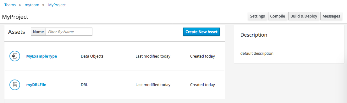
If the Workbench is empty the Project Authoring shows a quick import page. Clicking any of the example buttons below will install an example for you.
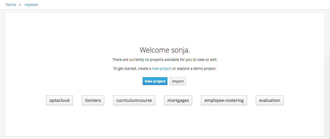
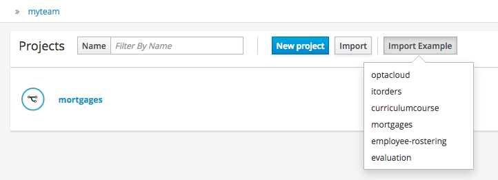
If the Workbench already contains Projects the examples can be imported with the "Import Example" button.
3.2.2. Add Project
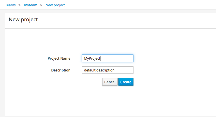
Alternatively, to importing an example, a new empty project can be created from the Project Authoring.
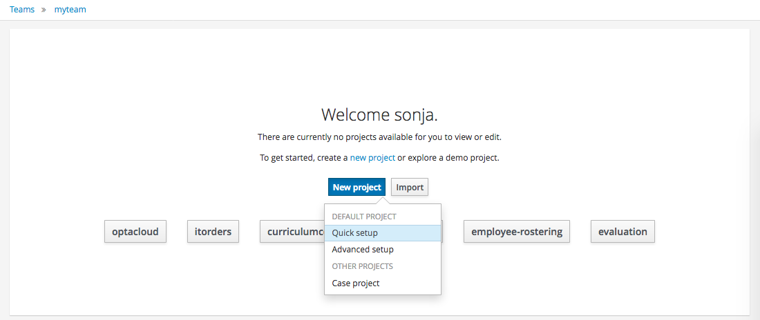
Select "Quick setup" and give the Project a name and optional description.
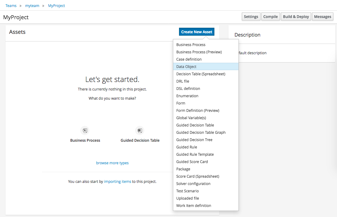
3.2.3. Define Data Model
After a Project has been created you need to define Types to be used by your rules.
Select "Data Object" from the "Create New Asset" menu.
|
You can also use types contained in existing JARs. Please consult the full documentation for details. |
Set the name and select a package for the new type.
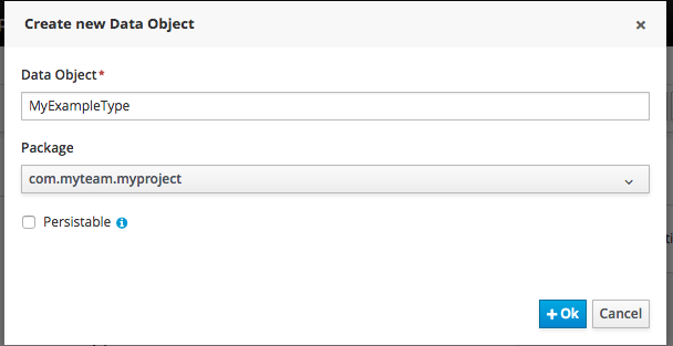
Click "+ add field" button and set a field name and type and click on "Create" to create a field for the type.
Click "Save" to update the model.
3.2.4. Define Rule
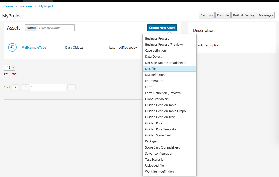
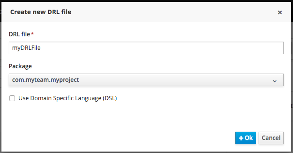
Select "DRL file" (for example) from the "Create New Asset" menu.
Enter a file name for the new rule.
|
Make sure you select the same package as the rule had. It is possible to have rules and data models in different packages, but let’s keep things simple for demo purposes. |
Enter a definition for the rule.
The definition process differs from asset type to asset type.
The full documentation has details about the different editors.
Once the rule has been defined it will need to be saved in the same way we saved the model.
3.2.5. Build and Deploy
Once rules have been defined within a project; the project can be built and deployed to the Workbench’s Maven Artifact Repository.
To build a project select the "Build & Deploy" from the Project Authoring.
Click "Build & Deploy" to build the project and deploy it to the Workbench’s Maven Artifact Repository.
When you select Build & Deploy the workbench will deploy to any repositories defined in the Dependency Management section of the pom in your workbench project. You can edit the pom.xml file associated with your workbench project under the Repository View of the project explorer. Details on dependency management in maven can be found here : http://maven.apache.org/guides/introduction/introduction-to-dependency-mechanism.html
If there are errors during the build process they will be reported in the "Messages" panel.
Now the project has been built and deployed; it can be referenced from your own projects as any other Maven Artifact.
The full documentation contains details about integrating projects with your own applications.
3.3. Administration
3.3.1. Administration overview
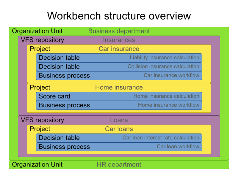
A workbench is structured with Organization Units, VFS repositories and projects:
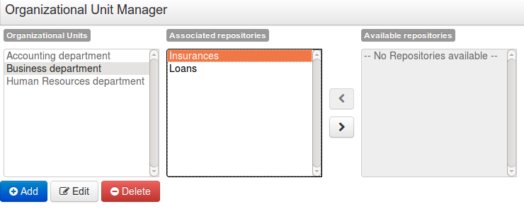
3.3.2. Organizational unit
Organization units are useful to model departments and divisions.
An organization unit can hold multiple repositories.
3.3.3. Repositories
Repositories are the place where assets are stored and each repository is organized by projects and belongs to a single organization unit.
Repositories are in fact a Virtual File System based storage, that by default uses GIT as backend. Such setup allows workbench to work with multiple backends and, in the same time, take full advantage of backend specifics features like in GIT case versioning, branching and even external access.
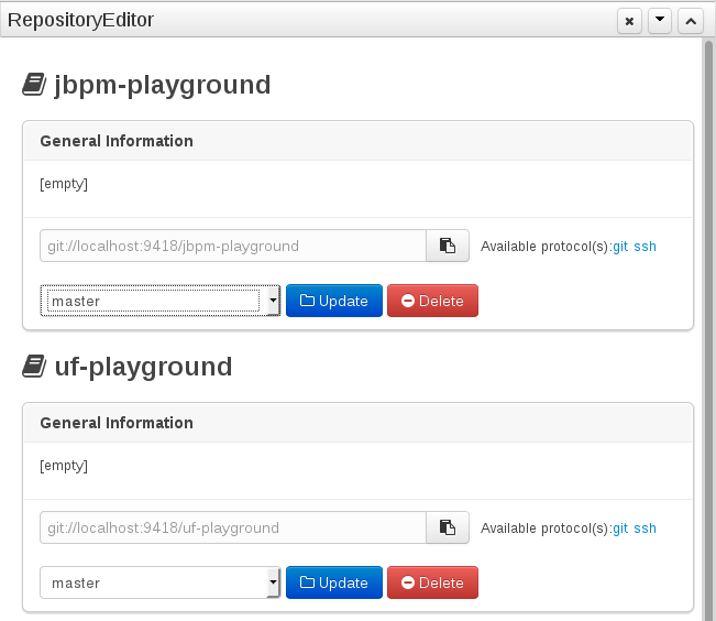
A new repository can be created from scratch or cloned from an existing repository.
One of the biggest advantage of using GIT as backend is the ability to clone a repository from external and use your preferred tools to edit and build your assets.
|
Never clone your repositories directly from .niogit directory. Use always the available protocol(s) displayed in repositories editor. |
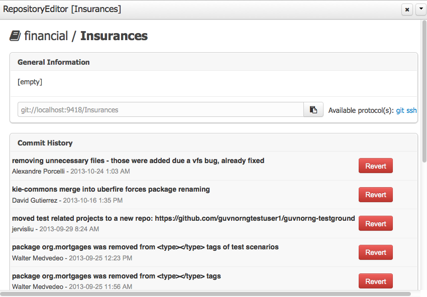
3.3.3.1. Repository Editor
One additional advantage to use GIT as backend is the possibility to revert your repository to a previous state. You can do it directly from the repository editor by browsing its commit history and clicking the Revert button.
3.4. Configuration
3.4.1. Basic user management
The workbench authenticates its users against the application server’s authentication and authorization (JAAS).
On JBoss EAP and WildFly, add a user with the script $JBOSS_HOME/bin/add-user.sh (or .bat):
$ ./add-user.sh
// Type: Application User
// Realm: empty (defaults to ApplicationRealm)
// Role: admin
There is no need to restart the application server.
3.4.2. Roles
The Workbench uses the following roles:
-
admin
-
analyst
-
developer
-
manager
-
user
3.4.2.1. Admin
Administrates the BPMS system.
-
Manages users
-
Manages VFS Repositories
-
Has full access to make any changes necessary
3.4.2.2. Developer
Developer can do almost everything admin can do, except clone repositories.
-
Manages rules, models, process flows, forms and dashboards
-
Manages the asset repository
-
Can create, build and deploy projects
-
Can use the JBDS connection to view processes
3.4.2.3. Analyst
Analyst is a weaker version of developer and does not have access to the asset repository or the ability to deploy projects.
3.4.2.4. Business user
Daily user of the system to take actions on business tasks that are required for the processes to continue forward. Works primarily with the task lists.
-
Does process management
-
Handles tasks and dashboards
3.4.2.5. Manager/Viewer-only User
Viewer of the system that is interested in statistics around the business processes and their performance, business indicators, and other reporting of the system and people who interact with the system.
-
Only has access to dashboards
3.5. Introduction
3.5.1. Log in and log out
Create a user with the role admin and log in with those credentials.
After successfully logging in, the account username is displayed at the top right. Click on it to review the roles of the current account.
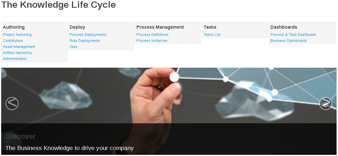
3.5.2. Home screen
After logging in, the home screen shows. The actual content of the home screen depends on the workbench variant (Drools, jBPM, …).
3.5.3. Workbench concepts
The Workbench is comprised of different logical entities:
-
Part
A Part is a screen or editor with which the user can interact to perform operations.
Example Parts are "Project Explorer", "Project Editor", "Guided Rule Editor" etc.
-
Perspective
A perspective is a logical grouping of related Panels and Parts.
The user can switch between perspectives by clicking on one of the top-level menu items; such as "Home", "Authoring", "Deploy" etc.
3.6. Changing the layout
3.6.1. Resizing
Move the mouse pointer over the panel splitter (a grey horizontal or vertical line in between panels).
The cursor will by changing indicate it is positioned correctly over the splitter. Press and hold the left mouse button and drag the splitter to the required position; then release the left mouse button.
3.7. Authoring (General)
3.7.1. Artifact Repository
Projects often need external artifacts in their classpath in order to build, for example a domain model JARs. The artifact repository holds those artifacts.
The Artifact Repository is a full blown Maven repository. It follows the semantics of a Maven remote repository: all snapshots are timestamped. But it is often stored on the local hard drive.
By default the artifact repository is stored under $WORKING_DIRECTORY/repositories/kie, but it can be overridden with the system property-Dorg.guvnor.m2repo.dir.
There is only 1 Maven repository per installation.
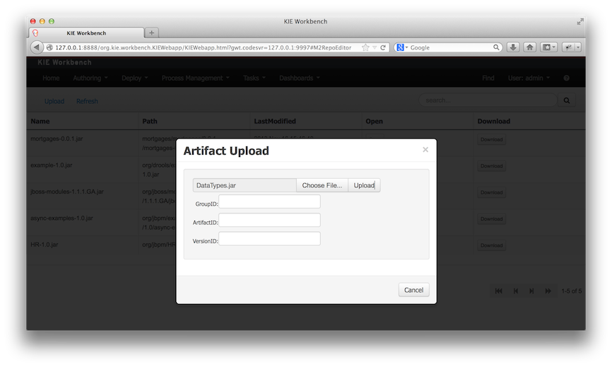
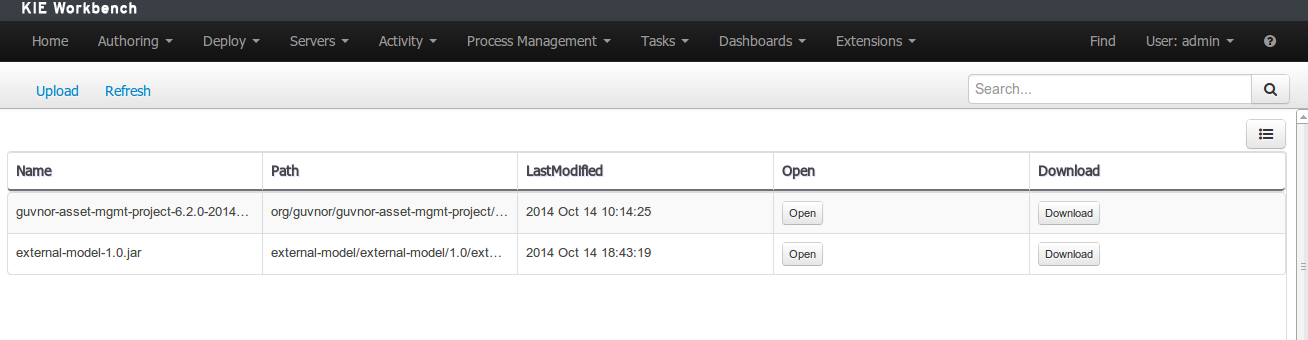
The Artifact Repository screen shows a list of the artifacts in the Maven repository:
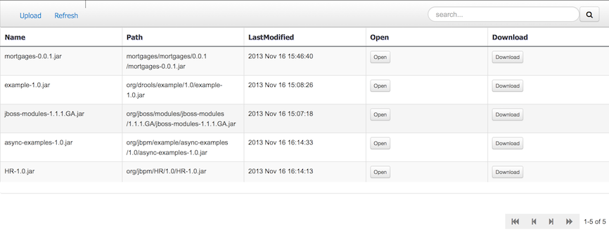
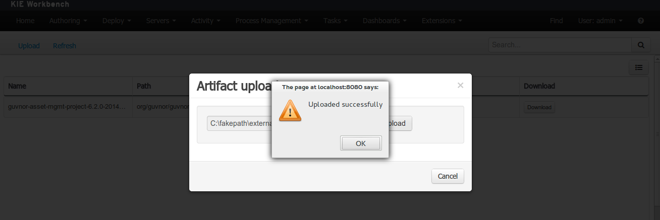
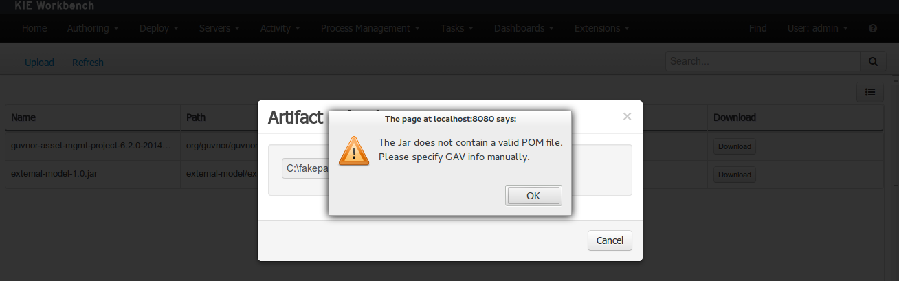
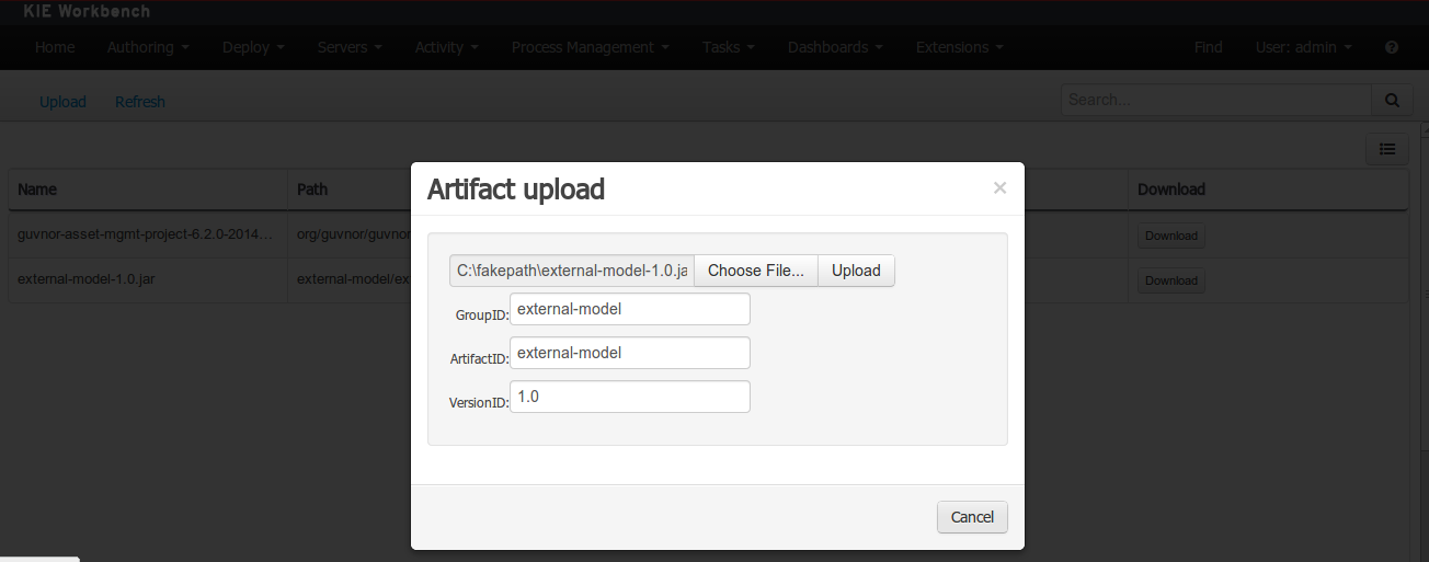
To add a new artifact to that Maven repository, either:
-
Use the upload button and select a JAR. If the JAR contains a POM file under
META-INF/maven(which every JAR build by Maven has), no further information is needed. Otherwise, a groupId, artifactId and version need be given too.
-
Using Maven,
mvn deployto that Maven repository. Refresh the list to make it show up.
|
This remote Maven repository is relatively simple. It does not support proxying, mirroring, … like Nexus or Archiva. |
3.7.2. Asset Editor
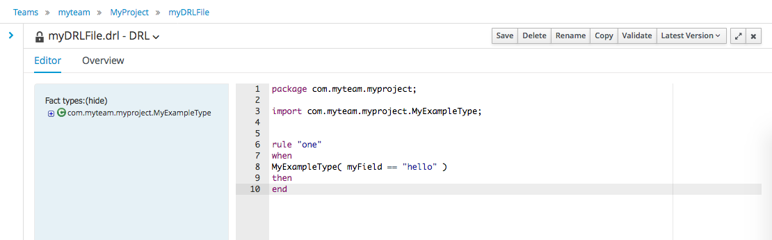
The Asset Editor is the principle component of the workbench User-Interface. It consists of two main views Editor and Overview.
-
The views
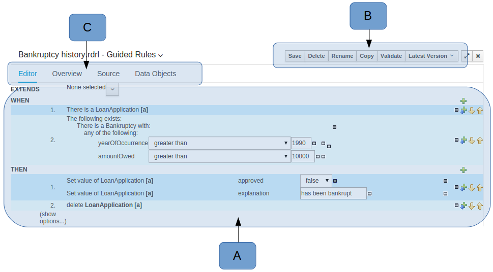 Figure 11. The Asset Editor - Editor tab
-
A : The editing area - exactly what form the editor takes depends on the Asset type. An asset can only be edited by one user at a time to avoid conflicts. When a user begins to edit an asset, a lock will automatically be acquired. This is indicated by a lock symbol appearing on the asset title bar as well as in the project explorer view (see Project Explorer for details). If a user starts editing an already locked asset a pop-up notification will appear to inform the user that the asset can’t currently be edited, as it is being worked on by another user. Changes will be prevented until the editing user saves or closes the asset, or logs out of the workbench. Session timeouts will also cause locks to be released. Every user further has the option to force a lock release, if required (see the Metadata section below).
-
B : This menu bar contains various actions for the Asset; such as Save, Rename, Copy etc. Note that saving, renaming and deleting are deactivated if the asset is locked by a different user.
-
C : Different views for asset content or asset information.
-
Editor shows the main editor for the asset
-
Overview contains the metadata and conversation views for this editor. Explained in more detail below.
-
Source shows the asset in plain DRL. Note: This tab is only visible if the asset content can be generated into DRL.
-
Data Objects contains the model available for authoring. By default only Data Objects that reside within the same package as the asset are available for authoring. Data Objects outside of this package can be imported to become available for authoring the asset.
-
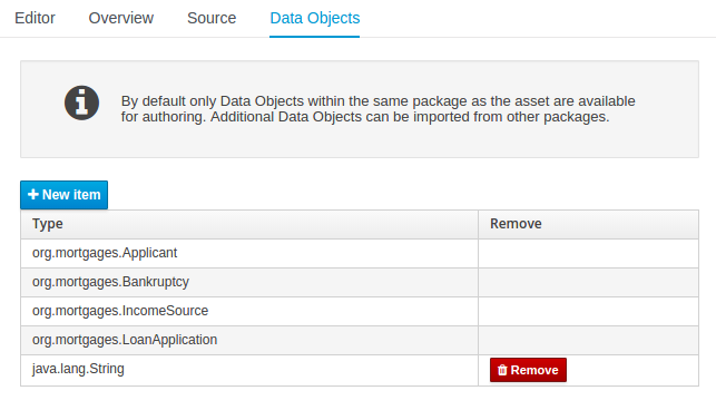 Figure 12. The Asset Editor - Data Objects tab
 -
-
Overview
-
A : General information about the asset and the asset’s description.
"Type:" The format name of the type of Asset.
"Description:" Description for the asset.
"Used in projects:" Names the projects where this rule is used.
"Last Modified:" Who made the last change and when.
"Created on:" Who created the asset and when.
-
B : Version history for the asset. Selecting a version loads the selected version into this editor.
-
C : Meta data (from the "Dublin Core" standard)
-
D : Comments regarding the development of the Asset can be recorded here.
.The Asset Editor - Overview tab image::Workbench/Authoring/AssetEditor/Overview.png[align="center"]
-
-
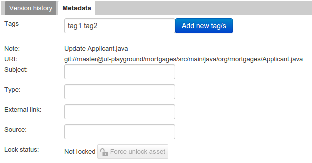
Metadata
-
A : Meta data:-
"Tags:" A tagging system for grouping the assets.
"Note:" A comment made when the Asset was last updated (i.e. why a change was made)
"URI:" URI to the asset inside the Git repository.
"Subject/Type/External link/Source" : Other miscellaneous meta data for the Asset.
"Lock status" : Shows the lock status of the asset and, if locked, allows to force unlocking the asset.
.The Metadata tab image::Workbench/Authoring/AssetEditor/Metadata.png[align="center"]
-
-
Locking
The Workbench supports pessimistic locking of assets. When one User starts editing an asset it is locked to change by other Users. The lock is held until a period of inactivity lapses, the Editor is closed or the application stopped and restarted. Locks can also be forcibly removed on the MetaData section of the Overview tab.
A "padlock" icon is shown in the Editor’s title bar and beside the asset in the Project Explorer when an asset is locked.
 Figure 13. The Asset Editor - Locked assets cannot be edited by other users
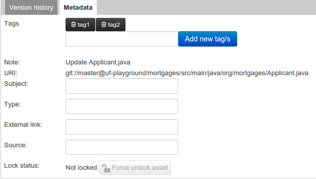
3.7.3. Tags Editor
Tags allow assets to be labelled with any number of tags that you define. These tags can be used to filter assets on the Project Explorer enabling "Tag filtering".
3.7.3.1. Creating Tags
To create tags you simply have to write them on the Tags input and press the "Add new Tag/s" button. The Tag Editor allows creating tags one by one or writing more than one separated with a white space.
Once you created new Tags they will appear over the Editor allowing you to remove them by pressing on them if you want.
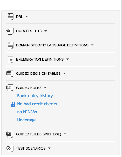
3.7.4. Project Explorer
The Project Explorer provides the ability to browse files in side the current Repository.
3.7.4.1. Initial view
If a file is currently being edited by another user, a lock symbol will be displayed in front of the file name. The symbol is blue in case the lock is owned by the currently authenticated user, otherwise black. Moving the mouse pointer over the lock symbol will display a tooltip providing the name of the user who is currently editing the file (and therefore owning the lock). To learn more about locking see Asset Editor for details.
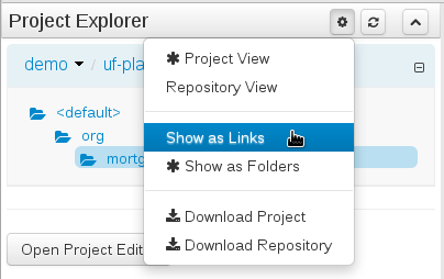
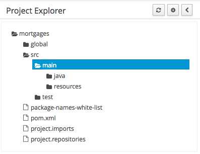
3.7.4.2. Different views
Project Explorer supports multiple views.
-
Project View
A simplified view of the underlying project structure. Certain system files are hidden from view.
-
Repository View
A complete view of the underlying project structure including all files; either user-defined or system generated.
Views can be selected by clicking on the icon within the Project Explorer, as shown below.
Both Project and Repository Views can be further refined by selecting either "Show as Folders" or "Show as Links".
3.7.4.3. Download Project or Repository
Download Download and Download Repository make it possible to download the project or repository as a zip file.
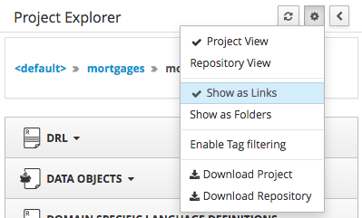
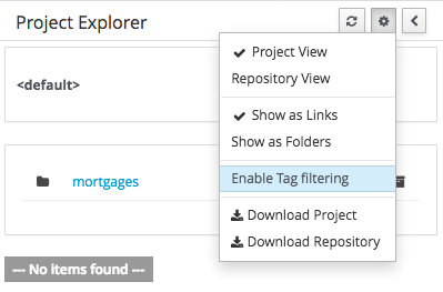
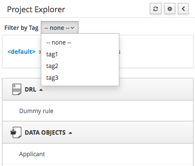
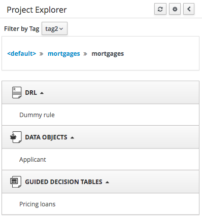
3.7.4.4. Filtering by Tag
To make easy view the elements on packages that contain a lot of assets, is possible to enabling the Tag filter, whichs allows you to filter the assets by their tags.
To see how to add tags to an asset look at: Tags Editor
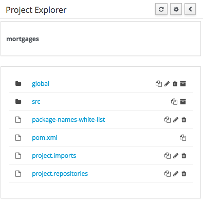
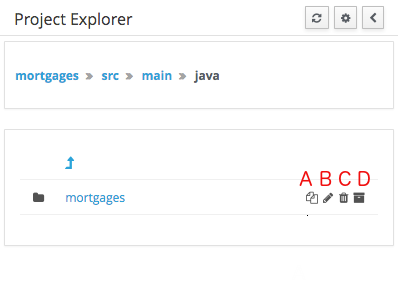
3.7.4.5. Copy, Rename, Delete and Download Actions
Copy, rename and delete actions are available on Links mode, for packages in of Project View and for files and directories in Repository View. Download action is available for directories. Download option downloads the selected the selected directory as a zip file.
-
A : Copy
-
B : Rename
-
C : Delete
-
D : Download
|
Workbench roadmap includes a refactoring and an impact analyses tools, but currenctly doesn’t have it. Until both tools are provided make sure that your changes (copy/rename/delete) on packages, files or directories doesn’t have a major impact on your project. In cases that your change had an unexcepcted impact, Workbench allows you to restore your repository using the Repository editor. |
|
Files locked by other users as well as directories that contain such files cannot be renamed or deleted until the corresponding locks are released. If that is the case the rename and delete symbols will be deactivated. To learn more about locking see Asset Editor for details. 
|
3.7.5. Project Editor
The Project Editor screen can be accessed from Project Explorer. Project Editor shows the settings for the currently active project.
Unlike most of the workbench editors, project editor edits more than one file. Showing everything that is needed for configuring the KIE project in one place.
3.7.5.1. Build & Deploy
Build & Depoy builds the current project and deploys the KJAR into the workbench internal Maven repository.
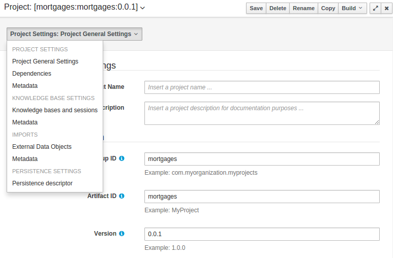
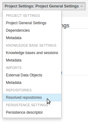
3.7.5.2. Project Settings
Project Settings edits the pom.xml file used by Maven.
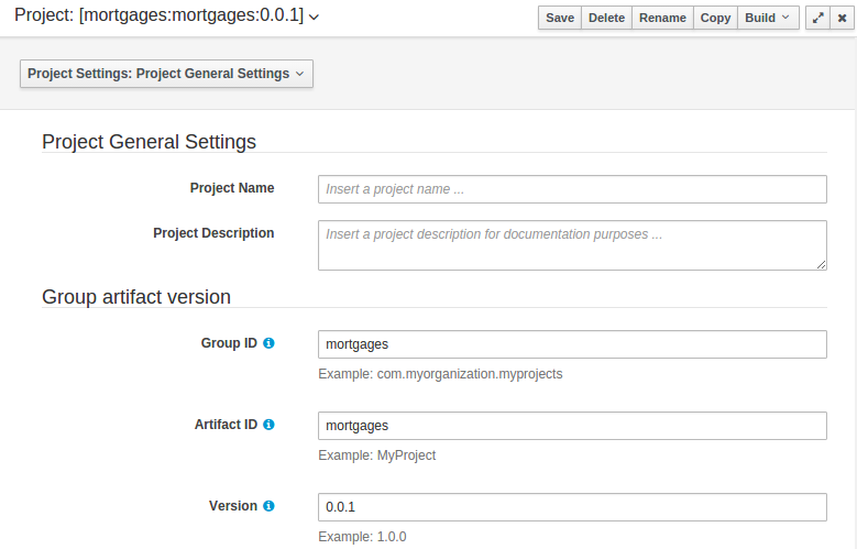
Project General Settings
General settings provide tools for project name and GAV-data (Group, Artifact, Version). GAV values are used as identifiers to differentiate projects and versions of the same project.
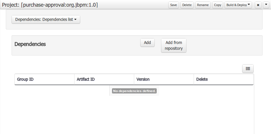
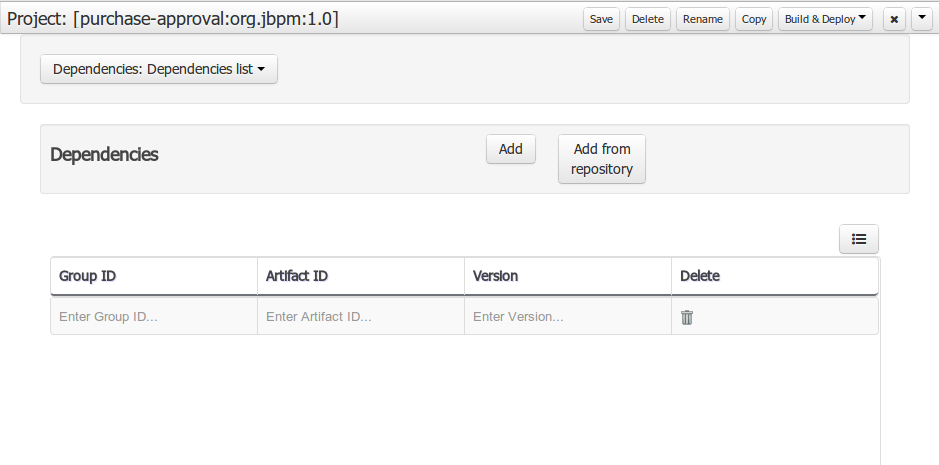
Dependencies
The project may have any number of either internal or external dependencies. Dependency is a project that has been built and deployed to a Maven repository. Internal dependencies are projects build and deployed in the same workbench as the project. External dependencies are retrieved from repositories outside of the current workbench. Each dependency uses the GAV-values to specify the project name and version that is used by the project.
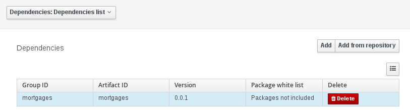
Classes and declared types in white listed packages show up as Data Objects that can be imported in assets. The full list is stored in package-name-white-list file that is stored in each project root.
Package white list has three modes:
-
All packages included: Every package defined in this jar is white listed.
-
Packages not included: None of the packages listed in this jar are white listed.
-
Some packages included: Only part of the packages in the jar are white listed.
Metadata
Metadata for the pom.xml file.
3.7.5.3. Knowledge Base Settings
Knowledge Base Settings edits the kmodule.xml file used by Drools.
|
For more information about the Knowledge Base properties, check the Drools Expert documentation for kmodule.xml. |
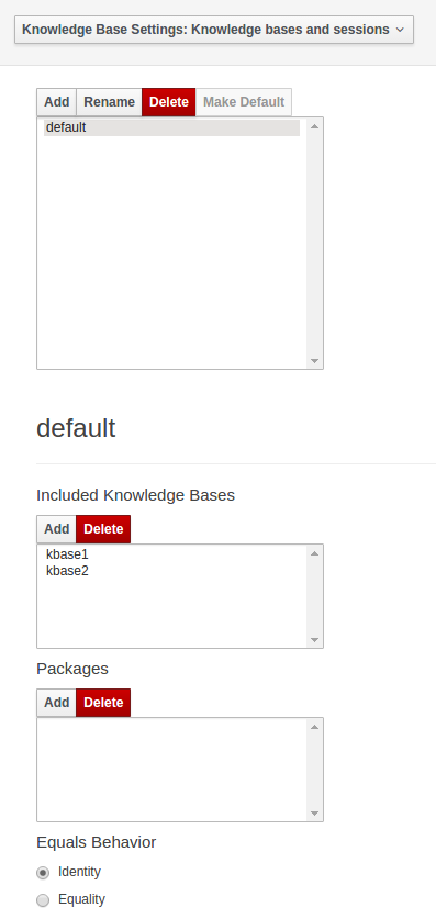
Knowledge bases and sessions
Knowledge bases and sessions lists the knowledge bases and the knowledge sessions specified for the project.
Lists all the knowledge bases by name. Only one knowledge base can be set as default.
Knowledge base can include other knowledge bases. The models, rules and any other content in the included knowledge base will be visible and usable by the currently selected knowledge base.
Rules and models are stored in packages. The packages property specifies what packages are included into this knowledge base.
Equals behavior is explained in the Drools Expert part of the documentation.
Event processing mode is explained in the Drools Fusion part of the documentation.
The table lists all the knowledge sessions in the selected knowledge base. There can be only one default of each type. The types are stateless and stateful. Clicking the pen-icon opens a popup that shows more properties for the knowledge session.
Metadata
Metadata for the kmodule.xml
3.7.5.4. Imports
Settings edits the project.imports file used by the workbench editors.
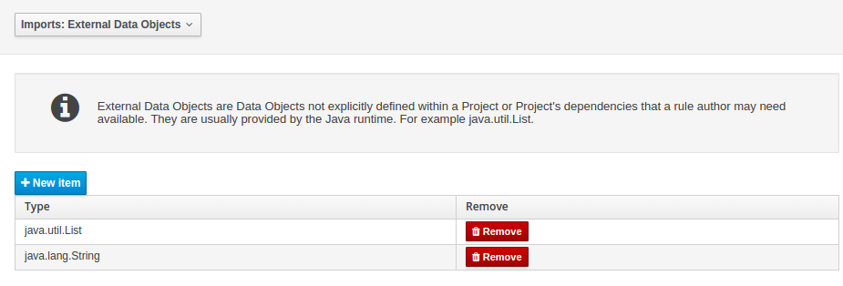
External Data Objects
Data Objects provided by the Java Runtime environment may need to be registered to be available to rule authoring where such Data Objects are not implicitly available as part of an existing Data Object defined within the Workbench or a Project dependency.
For example an Author may want to define a rule that checks for java.util.ArrayList in Working Memory.
If a domain Data Object has a field of type java.util.ArrayList there is no need create a registraton.
Metadata
Metadata for the project.imports file.
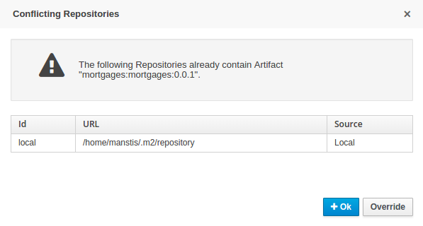
3.7.5.5. Duplicate GAV detection
When performing any of the following operations a check is now made against all Maven Repositories, resolved for the Project, for whether the Project’s GroupId, ArtifactId and Version pre-exist.
If a clash is found the operation is prevented; although this can be overridden by Users with the admin role.
|
The feature can be disabled by setting the System Property |
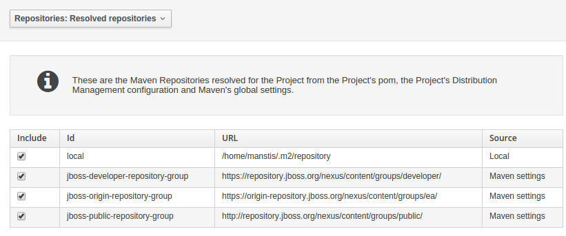
Resolved repositories are those discovered in:-
-
The Project’s
POMsection (or any parent<repositories>POM). -
The Project’s
POMsection.<distributionManagement> -
Maven’s global
settings.xmlconfiguration file.
Affected operations:-
-
Creation of new Managed Repositories.
-
Saving a Project defintion with the Project Editor.
-
Adding new Modules to a Managed Multi-Module Repository.
-
Saving the
pom.xmlfile. -
Build & installing a Project with the Project Editor.
-
Build & deploying a Project with the Project Editor.
-
Asset Management operations building, installing or deloying Projects.
-
RESToperations creating, installing or deploying Projects.
Users with the Admin role can override the list of Repositories checked using the "Repositories" settings in the Project Editor.
3.7.6. Validation
The Workbench provides a common and consistent service for users to understand whether files authored within the environment are valid.
3.7.6.1. Problem Panel
The Problems Panel shows real-time validation results of assets within a Project.
When a Project is selected from the Project Explorer the Problems Panel will refresh with validation results of the chosen Project.
When files are created, saved or deleted the Problems Panel content will update to show either new validation errors, or remove existing if a file was deleted.
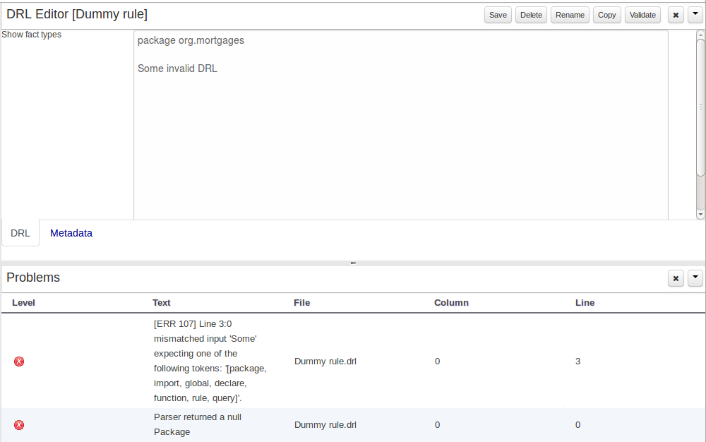
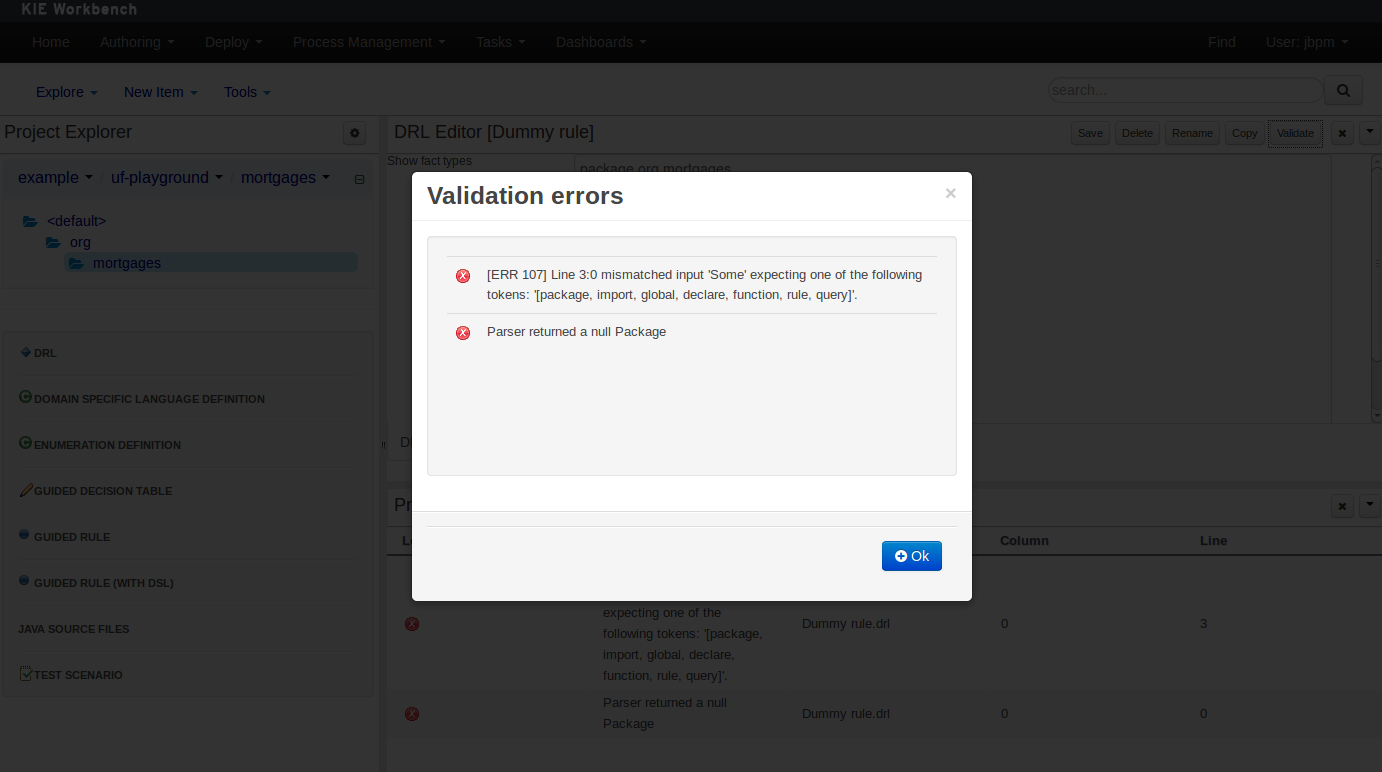
3.7.6.2. On demand validation
It is not always desirable to save a file in order to determine whether it is in a valid state.
All of the file editors provide the ability to validate the content before it is saved.
Clicking on the 'Validate' button shows validation errors, if any.
3.7.7. Data Modeller
3.7.7.1. First steps to create a data model
By default, a data model is always constrained to the context of a project. For the purpose of this tutorial, we will assume that a correctly configured project already exists and the authoring perspective is open.
To start the creation of a data model inside a project, take the following steps:
-
From the home panel, select the authoring perspective and select the given project.
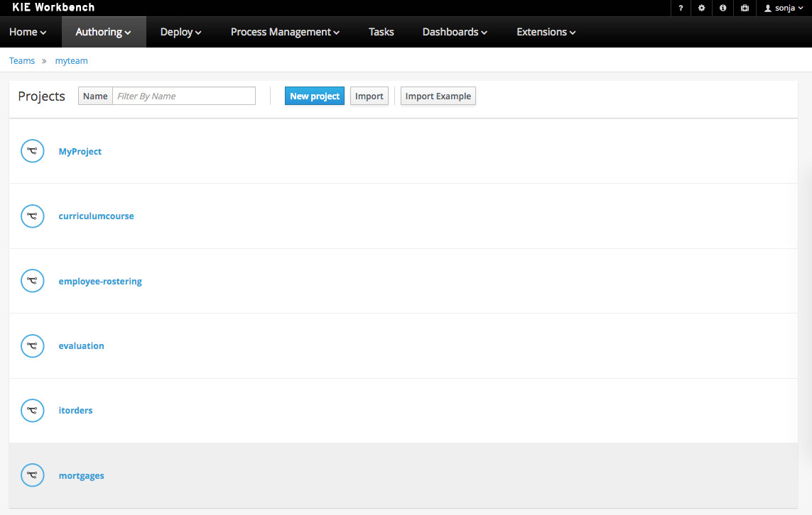 Figure 34. Go to authoring perspective and select a project
 -
Open the Data Modeller tool by clicking on a Data Object file, or using the "Create New Asset → Data Object" menu option.
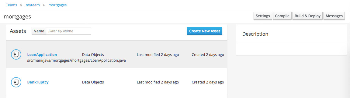 Figure 35. Click on a Data Object
This will start up the Data Modeller tool, which has the following general aspect:
The "Editor" tab is divided into the following sections:
-
The new field section is dedicated to the creation of new fields, and is opened when the "add field" button is pressed.
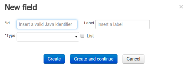 Figure 37. New field creation
 -
The Data Object’s "field browser" section displays a list with the data object fields.
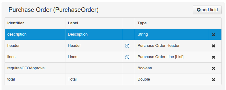 Figure 38. The Data Object’s field browser
 -
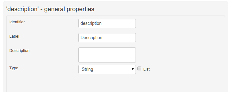
The "Data Object / Field general properties" section. This is the rightmost section of the Data Modeller editor and visualizes the "Data Object" or "Field" general properties, depending on user selection.
Data Object general properties can be selected by clicking on the Data Object Selector.
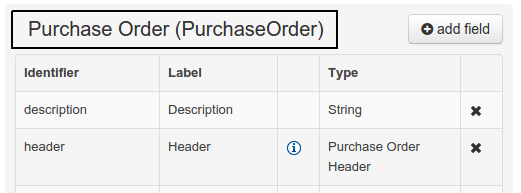 Figure 39. Data Object selector
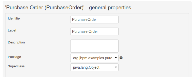 Figure 40. Data Object general properties
Field general properties can be selected by clicking on a field.
+
-
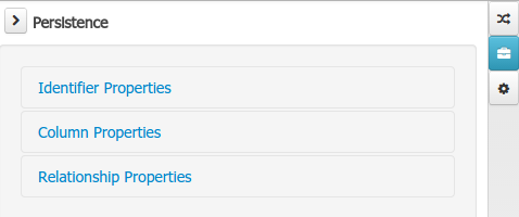
On workbench’s right side a new "Tool Bar" is provided that enables the selection of different context sensitive tool windows that will let the user do domain specific configurations. Currently four tool windows are provided for the following domains "Drools & jBPM", "OptaPlanner", "Persistence" and "Advanced" configurations.
 Figure 43. Data modeller Tool Bar
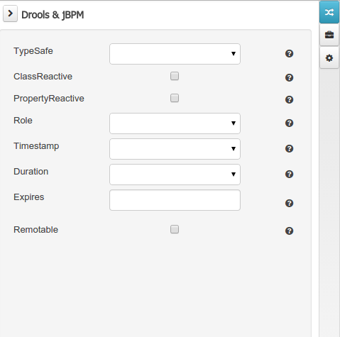 Figure 44. Drools & jBPM tool window
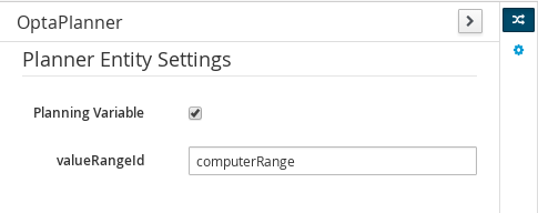 Figure 45. OptaPlanner tool window
To see and use the OptaPlanner tool window, the user needs to have the role
plannermgmt.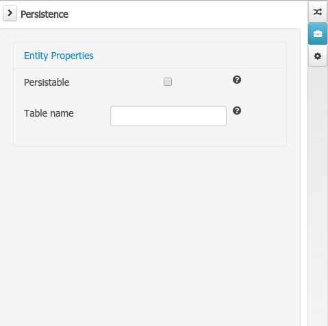 Figure 46. Persistence tool window
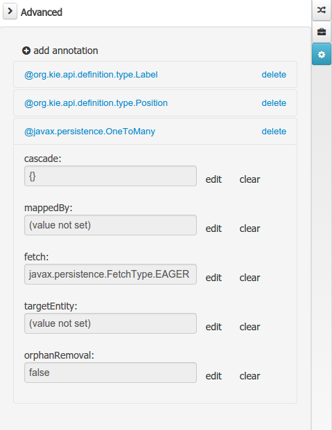 Figure 47. Advanced tool window
The "Source" tab shows an editor that allows the visualization and modification of the generated java code.
-
Round trip between the "Editor" and "Source" tabs is possible, and also source code preservation is provided. It means that not matter where the Java code was generated (e.g. Eclipse, Data modeller), the data modeller will only update the necessary code blocks to maintain the model updated.
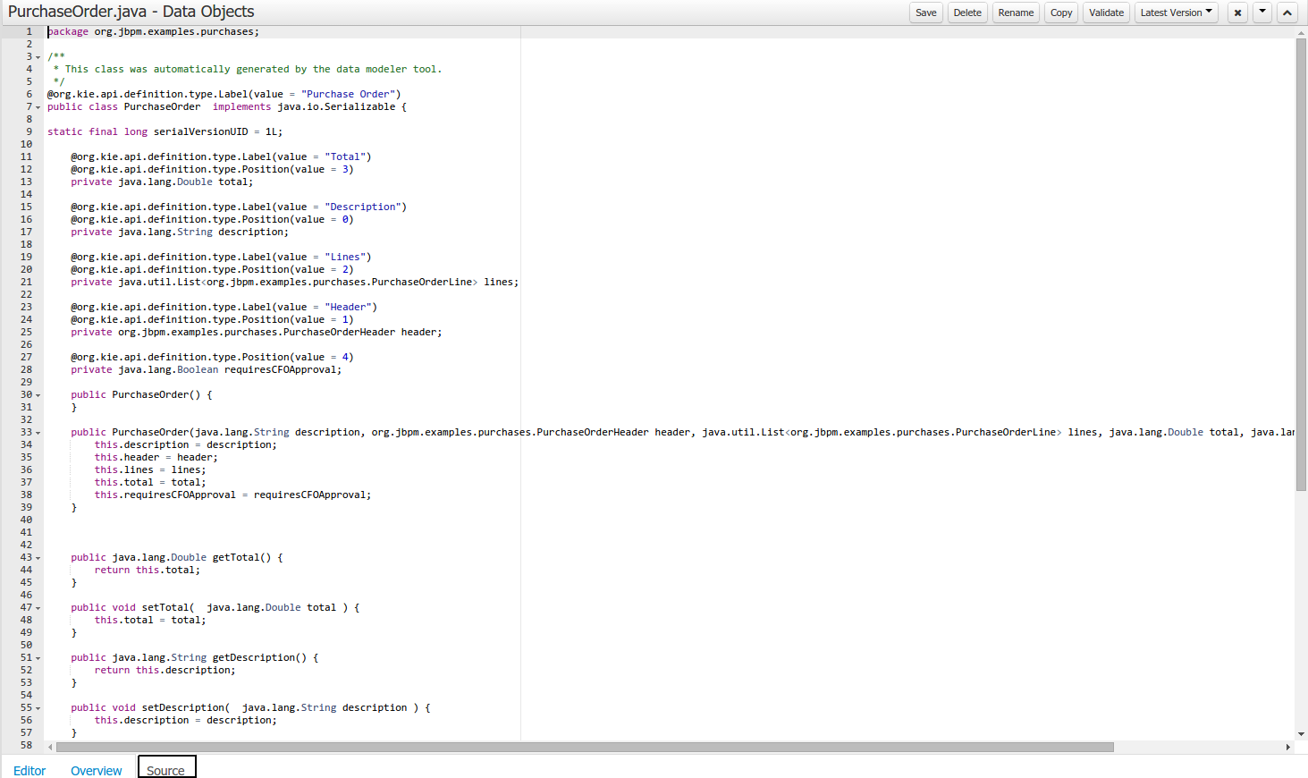 Figure 48. Source editor
The "Overview" tab shows the standard metadata and version information as the other workbench editors.
3.7.7.2. Data Objects
A data model consists of data objects which are a logical representation of some real-world data. Such data objects have a fixed set of modeller (or application-owned) properties, such as its internal identifier, a label, description, package etc. Besides those, a data object also has a variable set of user-defined fields, which are an abstraction of a real-world property of the type of data that this logical data object represents.
Creating a data object can be achieved using the workbench "New Item - Data Object" menu option.
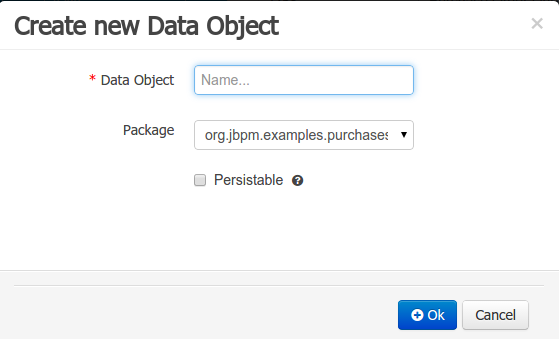
Both resource name and location are mandatory parameters. When the "Ok" button is pressed a new Java file will be created and a new editor instance will be opened for the file edition. The optional "Persistable" attribute will add by default configurations on the data object in order to make it a JPA entity. Use this option if your jBPM project needs to store data object’s information in a data base.
3.7.7.3. Properties & relationships
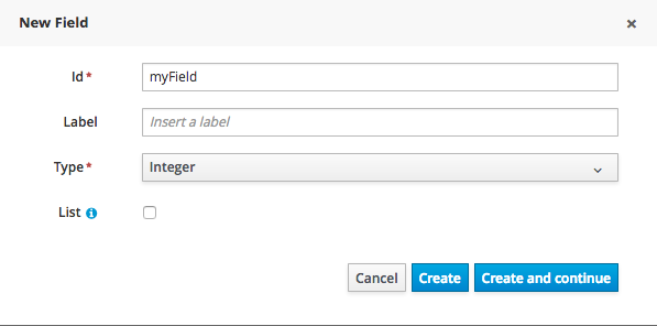
Once the data object has been created, it now has to be completed by adding user-defined properties to its definition. This can be achieved by pressing the "add field" button. The "New Field" dialog will be opened and the new field can be created by pressing the "Create" button. The "Create and continue" button will also add the new field to the Data Object, but won’t close the dialog. In this way multiple fields can be created avoiding the popup opening multiple times. The following fields can (or must) be filled out:
-
The field’s internal identifier (mandatory). The value of this field must be unique per data object, i.e. if the proposed identifier already exists within current data object, an error message will be displayed.
-
A label (optional): as with the data object definition, the user can define a user-friendly label for the data object field which is about to be created. This has no further implications on how fields from objects of this data object will be treated. If a label is defined, then this is how the field will be displayed throughout the data modeller tool.
-
A field type (mandatory): each data object field needs to be assigned with a type.
This type can be either of the following:
-
A 'primitive java object' type: these include most of the object equivalents of the standard Java primitive types, such as Boolean, Short, Float, etc, as well as String, Date, BigDecimal and BigInteger.
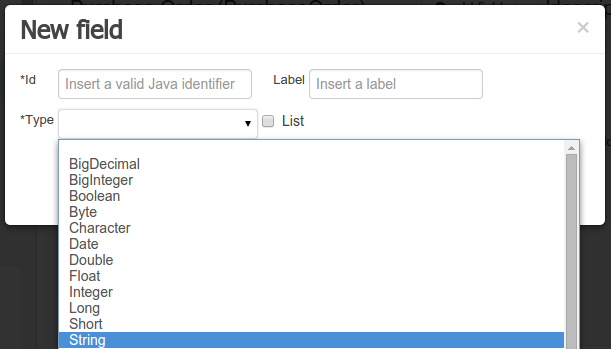 Figure 50. Primitive object field types
 -
A 'data object' type: any user defined data object automatically becomes a candidate to be defined as a field type of another data object, thus enabling the creation of relationships between them. A data object field can be created either in 'single' or in 'multiple' form, the latter implying that the field will be defined as a collection of this type, which will be indicated by selecting "List" checkbox.
-

+
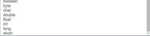
+ .. A 'primitive java' type: these include java primitive types byte, short, int, long, float, double, char and boolean.
+
+
+
When finished introducing the initial information for a new field, clicking the 'Create' button will add the newly created field to the end of the data object’s fields table below:
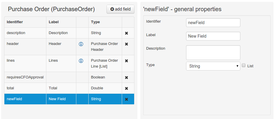
The new field will also automatically be selected in the data object’s field list, and its properties will be shown in the Field general properties editor. Additionally the field properties will be loaded in the different tool windows, in this way the field will be ready for edition in whatever selected tool window.
At any time, any field (without restrictions) can be deleted from a data object definition by clicking on the corresponding 'x' icon in the data object’s fields table.
3.7.7.4. Additional options
As stated before, both Data Objects as well as Fields require some of their initial properties to be set upon creation. Additionally there are three domains of properties that can be configured for a given Data Object. A domain is basically a set of properties related to a given business area. Current available domains are, "Drools & jJBPM", "Persistence" and the "Advanced" domain. To work on a given domain the user should select the corresponding "Tool window" (see below) on the right side toolbar. Every tool window usually provides two editors, the "Data Object" level editor and the "Field" level editor, that will be shown depending on the last selected item, the Data Object or the Field.
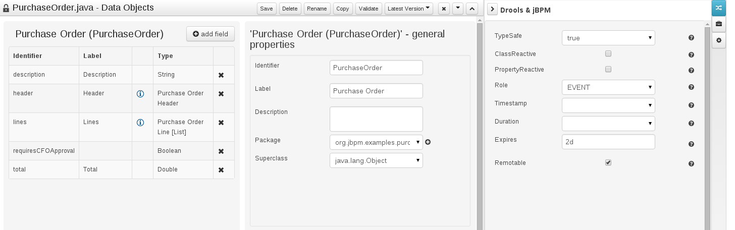
Drools & jBPM domain
The Drools & jBPM domain editors manages the set of Data Object or Field properties related to drools applications.
The Drools & jBPM object editor manages the object level drools properties
-
TypeSafe: this property allows to enable/disable the type safe behaviour for current type. By default all type declarations are compiled with type safety enabled. (See Drools for more information on this matter).
-
ClassReactive: this property allows to mark this type to be treated as "Class Reactive" by the Drools engine. (See Drools for more information on this matter).
-
PropertyReactive: this property allows to mark this type to be treated as "Property Reactive" by the Drools engine. (See Drools for more information on this matter).
-
Role: this property allows to configure how the Drools engine should handle instances of this type: either as regular facts or as events. By default all types are handled as a regular fact, so for the time being the only value that can be set is "Event" to declare that this type should be handled as an event. (See Drools Fusion for more information on this matter).
-
Timestamp: this property allows to configure the "timestamp" for an event, by selecting one of his attributes. If set the engine will use the timestamp from the given attribute instead of reading it from the Session Clock. If not, the engine will automatically assign a timestamp to the event. (See Drools Fusion for more information on this matter).
-
Duration: this property allows to configure the "duration" for an event, by selecting one of his attributes. If set the engine will use the duration from the given attribute instead of using the default event duration = 0. (See Drools Fusion for more information on this matter).
-
Expires: this property allows to configure the "time offset" for an event expiration. If set, this value must be a temporal interval in the form: [d][#h][#m][#s][[ms]] Where [ ] means an optional parameter and # means a numeric value. e.g.: 1d2h, means one day and two hours. (See Drools Fusion for more information on this matter).
-
Remotable: If checked this property makes the Data Object available to be used with jBPM remote services as REST, JMS and WS. (See jBPM for more information on this matter).
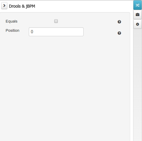
The Drools & jBPM object editor manages the field level drools properties
-
Equals: checking this property for a Data Object field implies that it will be taken into account, at the code generation level, for the creation of both the equals() and hashCode() methods in the generated Java class. We will explain this in more detail in the following section.
-
Position: this field requires a zero or positive integer. When set, this field will be interpreted by the Drools engine as a positional argument (see the section below and also the Drools documentation for more information on this subject).
Persistence domain
The Persistence domain editors manages the set of Data Object or Field properties related to persistence.
Persistence domain object editor manages the object level persistence properties
-
Persistable: this property allows to configure current Data Object as persistable.
-
Table name: this property allows to set a user defined database table name for current Data Object.
The persistence domain field editor manages the field level persistence properties and is divided in three sections.
A persistable Data Object should have one and only one field defined as the Data Object identifier. The identifier is typically a unique number that distinguishes a given Data Object instance from all other instances of the same class.
-
Is Identifier: marks current field as the Data Object identifier. A persistable Data Object should have one and only one field marked as identifier, and it should be a base java type, like String, Integer, Long, etc. A field that references a Data Object, or is a multiple field can not be marked as identifier. And also composite identifiers are not supported in this version. When a persistable Data Object is created an identifier field is created by default with the properly initializations, it’s strongly recommended to use this identifier.
-
Generation Strategy: the generation strategy establishes how the identifier values will be automatically generated when the Data Object instances are created and stored in a database. (e.g. by the forms associated to jBPM processes human tasks.) When the by default Identifier field is created, the generation strategy will be also automatically set and it’s strongly recommended to use this configuration.
-
Sequence Generator: the generator represents the seed for the values that will be used by the Generation Strategy. When the by default Identifier field is created the Sequence Generator will be also automatically generated and properly configured to be used by the Generation Strategy.
The column properties section enables the customization of some properties of the database column that will store the field value.
-
Column name: optional value that sets the database column name for the given field.
-
Unique: When checked the unique property establishes that current field value should be a unique key when stored in the database. (if not set the default value is false)
-
Nullable: When checked establishes that current field value can be null when stored in a database. (if not set the default value is true)
-
Insertable: When checked establishes that column will be included in SQL INSERT statements generated by the persistence provider. (if not set the default value is true)
-
Updatable: When checked establishes that the column will be included SQL UPDATE statements generated by the persistence provider. (if not set the default value is true)
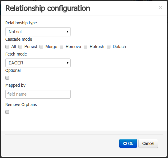
When the field’s type is a Data Object type, or a list of a Data Object type a relationship type should be set in order to let the persistence provider to manage the relation. Fortunately this relation type is automatically set when such kind of fields are added to an already marked as persistable Data Object. The relationship type is set by the following popup.
-
Relationship type: sets the type of relation from one of the following options:
One to one: typically used for 1:1 relations where "A is related to one instance of B", and B exists only when A exists. e.g. PurchaseOrder → PurchaseOrderHeader (a PurchaseOrderHeader exists only if the PurchaseOrder exists)
One to many: typically used for 1:N relations where "A is related to N instances of B", and the related instances of B exists only when A exists. e.g. PurchaseOrder → PurchaseOrderLine (a PurchaseOrderLine exists only if the PurchaseOrder exists)
Many to one: typically used for 1:1 relations where "A is related to one instance of B", and B can exist even without A. e.g. PurchaseOrder → Client (a Client can exist in the database even without an associated PurchaseOrder)
Many to many: typically used for N:N relations where "A can be related to N instances of B, and B can be related to M instances of A at the same time", and both B an A instances can exits in the database independently of the related instances. e.g. Course → Student. (Course can be related to N Students, and a given Student can attend to M courses)
When a field of type "Data Object" is added to a given persistable Data Object, the "Many to One" relationship type is generated by default.
And when a field of type "list of Data Object" is added to a given persistable Data Object , the "One to Many" relationship is generated by default.
-
Cascade mode: Defines the set of cascadable operations that are propagated to the associated entity. The value cascade=ALL is equivalent to cascade={PERSIST, MERGE, REMOVE, REFRESH}. e.g. when A → B, and cascade "PERSIST or ALL" is set, if A is saved, then B will be also saved.
The by default cascade mode created by the data modeller is "ALL" and it’s strongly recommended to use this mode when Data Objects are being used by jBPM processes and forms.
-
Fetch mode: Defines how related data will be fetched from database at reading time.
EAGER: related data will be read at the same time. e.g. If A → B, when A is read from database B will be read at the same time.
LAZY: reading of related data will be delayed usually to the moment they are required. e.g. If PurchaseOrder → PurchaseOrderLine the lines reading will be postponed until a method "getLines()" is invoked on a PurchaseOrder instance.
The default fetch mode created by the data modeller is "EAGER" and it’s strongly recommended to use this mode when Data Objects are being used by jBPM processes and forms.
-
Optional: establishes if the right side member of a relationship can be null.
-
Mapped by: used for reverse relations.
Advanced domain
The advanced domain enables the configuration of whatever parameter set by the other domains as well as the adding of arbitrary parameters. As it will be shown in the code generation section every "Data Object / Field" parameter is represented by a java annotation. The advanced mode enables the configuration of this annotations.
The advanced domain editor has the same shape for both Data Object and Field.
The following operations are available
-
delete: enables the deletion of a given Data Object or Field annotation.
-
clear: clears a given annotation parameter value.
-
edit: enables the edition of a given annotation parameter value.
-
add annotation: The add annotation button will start a wizard that will let the addition of whatever java annotation available in the project dependencies.
Add annotation wizard step #1: the first step of the wizard requires the entering of a fully qualified class name of an annotation, and by pressing the "search" button the annotation definition will be loaded into the wizard. Additionally when the annotation definition is loaded, different wizard steps will be created in order to enable the completion of the different annotation parameters. Required parameters will be marked with "*".
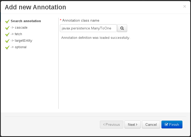 Figure 60. Annotation definition loaded into the wizard.
Whenever it’s possible the wizard will provide a suitable editor for the given parameters.
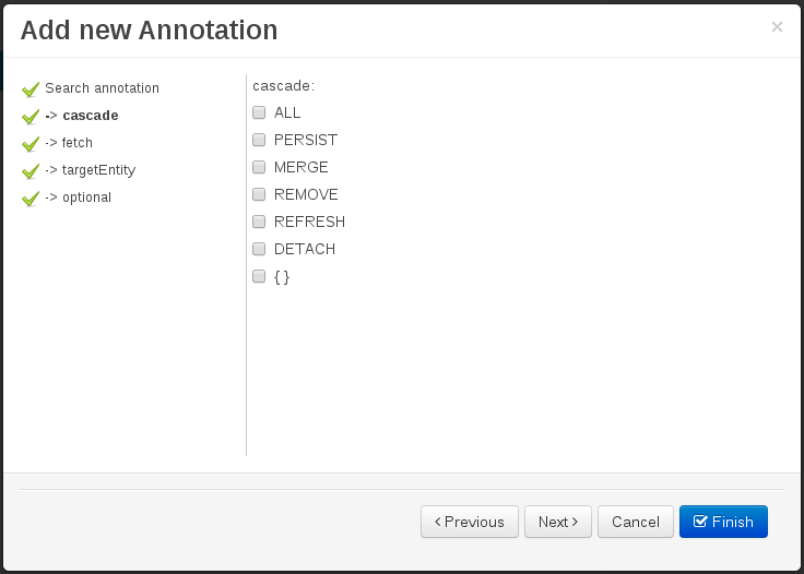 Figure 61. Automatically generated enum values editor for an Enumeration annotation parameter.
A generic parameter editor will be provided when it’s not possible to calculate a customized editor
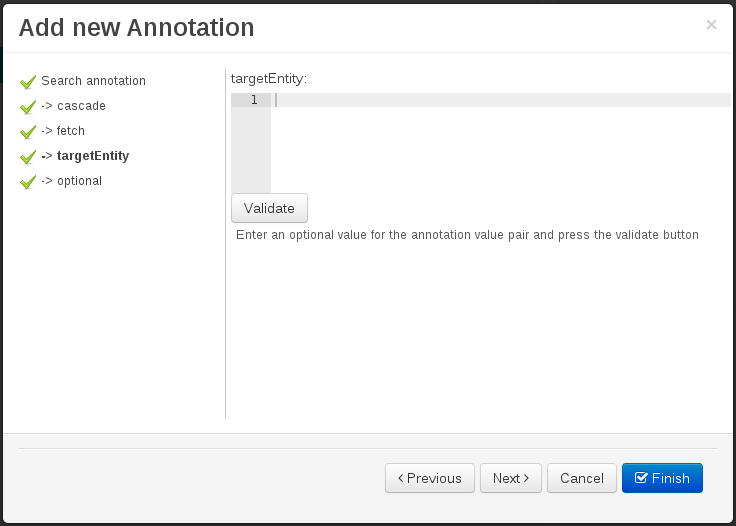 Figure 62. Generic annotation parameter editor
When all required parameters has been entered and validated, the finish button will be enabled and the wizard can be completed by adding the annotation to the given Data Object or Field.
3.7.7.5. Generate data model code.
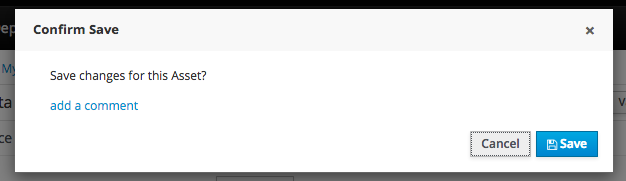
The data model in itself is merely a visual tool that allows the user to define high-level data structures, for them to interact with the Drools Engine on the one hand, and the jBPM platform on the other. In order for this to become possible, these high-level visual structures have to be transformed into low-level artifacts that can effectively be consumed by these platforms. These artifacts are Java POJOs (Plain Old Java Objects), and they are generated every time the data model is saved, by pressing the "Save" button in the top Data Modeller Menu. Additionally when the user round trip between the "Editor" and "Source" tab, the code is auto generated to maintain the consistency with the Editor view and vice versa.

The resulting code is generated according to the following transformation rules:
-
The data object’s identifier property will become the Java class’s name. It therefore needs to be a valid Java identifier.
-
The data object’s package property becomes the Java class’s package declaration.
-
The data object’s superclass property (if present) becomes the Java class’s extension declaration.
-
The data object’s label and description properties will translate into the Java annotations "@org.kie.api.definition.type.Label" and "@org.kie.api.definition.type.Description", respectively. These annotations are merely a way of preserving the associated information, and as yet are not processed any further.
-
The data object’s role property (if present) will be translated into the "@org.kie.api.definition.type.Role" Java annotation, that IS interpreted by the application platform, in the sense that it marks this Java class as a Drools Event Fact-Type.
-
The data object’s type safe property (if present) will be translated into the "@org.kie.api.definition.type.TypeSafe Java annotation. (see Drools)
-
The data object’s class reactive property (if present) will be translated into the "@org.kie.api.definition.type.ClassReactive Java annotation. (see Drools)
-
The data object’s property reactive property (if present) will be translated into the "@org.kie.api.definition.type.PropertyReactive Java annotation. (see Drools)
-
The data object’s timestamp property (if present) will be translated into the "@org.kie.api.definition.type.Timestamp Java annotation. (see Drools)
-
The data object’s duration property (if present) will be translated into the "@org.kie.api.definition.type.Duration Java annotation. (see Drools)
-
The data object’s expires property (if present) will be translated into the "@org.kie.api.definition.type.Expires Java annotation. (see Drools)
-
The data object’s remotable property (if present) will be translated into the "@org.kie.api.remote.Remotable Java annotation. (see jBPM)
A standard Java default (or no parameter) constructor is generated, as well as a full parameter constructor, i.e. a constructor that accepts as parameters a value for each of the data object’s user-defined fields.
The data object’s user-defined fields are translated into Java class fields, each one of them with its own getter and setter method, according to the following transformation rules:
-
The data object field’s identifier will become the Java field identifier. It therefore needs to be a valid Java identifier.
-
The data object field’s type is directly translated into the Java class’s field type. In case the field was declared to be multiple (i.e. 'List'), then the generated field is of the "java.util.List" type.
-
The equals property: when it is set for a specific field, then this class property will be annotated with the "@org.kie.api.definition.type.Key" annotation, which is interpreted by the Drools Engine, and it will 'participate' in the generated equals() method, which overwrites the equals() method of the Object class. The latter implies that if the field is a 'primitive' type, the equals method will simply compares its value with the value of the corresponding field in another instance of the class. If the field is a sub-entity or a collection type, then the equals method will make a method-call to the equals method of the corresponding data object’s Java class, or of the java.util.List standard Java class, respectively.
If the equals property is checked for ANY of the data object’s user defined fields, then this also implies that in addition to the default generated constructors another constructor is generated, accepting as parameters all of the fields that were marked with Equals. Furthermore, generation of the equals() method also implies that also the Object class’s hashCode() method is overwritten, in such a manner that it will call the hashCode() methods of the corresponding Java class types (be it 'primitive' or user-defined types) for all the fields that were marked with Equals in the Data Model.
-
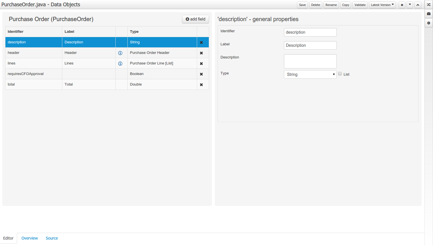
The position property: this field property is automatically set for all user-defined fields, starting from 0, and incrementing by 1 for each subsequent new field. However the user can freely changes the position among the fields. At code generation time this property is translated into the "@org.kie.api.definition.type.Position" annotation, which can be interpreted by the Drools Engine. Also, the established property order determines the order of the constructor parameters in the generated Java class.
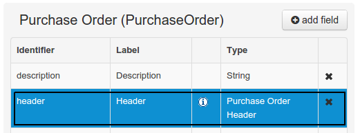
As an example, the generated Java class code for the Purchase Order data object, corresponding to its definition as shown in the following figure purchase_example.jpg is visualized in the figure at the bottom of this chapter. Note that the two of the data object’s fields, namely 'header' and 'lines' were marked with Equals, and have been assigned with the positions 2 and 1, respectively).
    package org.jbpm.examples.purchases;

    /**
    * This class was automatically generated by the data modeler tool.
    */
    @org.kie.api.definition.type.Label("Purchase Order")
    @org.kie.api.definition.type.TypeSafe(true)
    @org.kie.api.definition.type.Role(org.kie.api.definition.type.Role.Type.EVENT)
    @org.kie.api.definition.type.Expires("2d")
    @org.kie.api.remote.Remotable
    public class PurchaseOrder implements java.io.Serializable
    {

    static final long serialVersionUID = 1L;

    @org.kie.api.definition.type.Label("Total")
    @org.kie.api.definition.type.Position(3)
    private java.lang.Double total;

    @org.kie.api.definition.type.Label("Description")
    @org.kie.api.definition.type.Position(0)
    private java.lang.String description;

    @org.kie.api.definition.type.Label("Lines")
    @org.kie.api.definition.type.Position(2)
    @org.kie.api.definition.type.Key
    private java.util.List<org.jbpm.examples.purchases.PurchaseOrderLine> lines;

    @org.kie.api.definition.type.Label("Header")
    @org.kie.api.definition.type.Position(1)
    @org.kie.api.definition.type.Key
    private org.jbpm.examples.purchases.PurchaseOrderHeader header;

    @org.kie.api.definition.type.Position(4)
    private java.lang.Boolean requiresCFOApproval;

    public PurchaseOrder()
    {
    }

    public java.lang.Double getTotal()
    {
    return this.total;
    }

    public void setTotal(java.lang.Double total)
    {
    this.total = total;
    }

    public java.lang.String getDescription()
    {
    return this.description;
    }

    public void setDescription(java.lang.String description)
    {
    this.description = description;
    }

    public java.util.List<org.jbpm.examples.purchases.PurchaseOrderLine> getLines()
    {
    return this.lines;
    }

    public void setLines(java.util.List<org.jbpm.examples.purchases.PurchaseOrderLine> lines)
    {
    this.lines = lines;
    }

    public org.jbpm.examples.purchases.PurchaseOrderHeader getHeader()
    {
    return this.header;
    }

    public void setHeader(org.jbpm.examples.purchases.PurchaseOrderHeader header)
    {
    this.header = header;
    }

    public java.lang.Boolean getRequiresCFOApproval()
    {
    return this.requiresCFOApproval;
    }

    public void setRequiresCFOApproval(java.lang.Boolean requiresCFOApproval)
    {
    this.requiresCFOApproval = requiresCFOApproval;
    }

    public PurchaseOrder(java.lang.Double total, java.lang.String description,
    java.util.List<org.jbpm.examples.purchases.PurchaseOrderLine> lines,
    org.jbpm.examples.purchases.PurchaseOrderHeader header,
    java.lang.Boolean requiresCFOApproval)
    {
    this.total = total;
    this.description = description;
    this.lines = lines;
    this.header = header;
    this.requiresCFOApproval = requiresCFOApproval;
    }

    public PurchaseOrder(java.lang.String description,
    org.jbpm.examples.purchases.PurchaseOrderHeader header,
    java.util.List<org.jbpm.examples.purchases.PurchaseOrderLine> lines,
    java.lang.Double total, java.lang.Boolean requiresCFOApproval)
    {
    this.description = description;
    this.header = header;
    this.lines = lines;
    this.total = total;
    this.requiresCFOApproval = requiresCFOApproval;
    }

    public PurchaseOrder(
    java.util.List<org.jbpm.examples.purchases.PurchaseOrderLine> lines,
    org.jbpm.examples.purchases.PurchaseOrderHeader header)
    {
    this.lines = lines;
    this.header = header;
    }

    @Override
    public boolean equals(Object o)
    {
    if (this == o)
    return true;
    if (o == null || getClass() != o.getClass())
    return false;
    org.jbpm.examples.purchases.PurchaseOrder that = (org.jbpm.examples.purchases.PurchaseOrder) o;
    if (lines != null ? !lines.equals(that.lines) : that.lines != null)
    return false;
    if (header != null ? !header.equals(that.header) : that.header != null)
    return false;
    return true;
    }

    @Override
    public int hashCode()
    {
    int result = 17;
    result = 31 * result + (lines != null ? lines.hashCode() : 0);
    result = 31 * result + (header != null ? header.hashCode() : 0);
    return result;
    }

    }
3.7.7.6. Using external models
Using an external model means the ability to use a set for already defined POJOs in current project context. In order to make those POJOs available a dependency to the given JAR should be added. Once the dependency has been added the external POJOs can be referenced from current project data model.
There are two ways to add a dependency to an external JAR file:
-
Dependency to a JAR file already installed in current local M2 repository (typically associated the the user home).
-
Dependency to a JAR file installed in current KIE Workbench/Drools Workbench "Guvnor M2 repository". (internal to the application)
Dependency to a JAR file in local M2 repository
To add a dependency to a JAR file in local M2 repository follow this steps.
When project is saved the POJOs defined in the external file will be available.
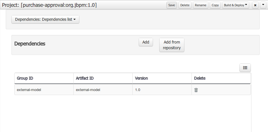
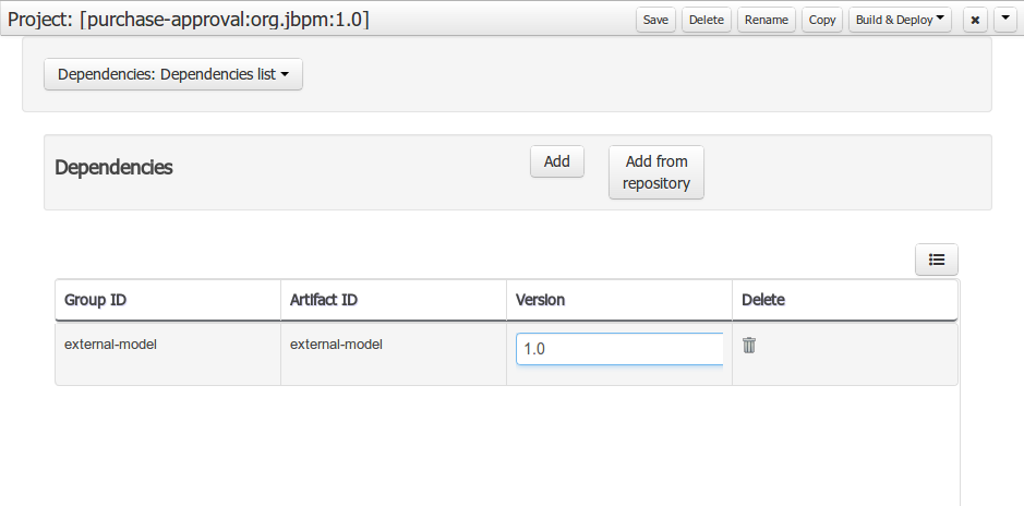
Dependency to a JAR file in current "Guvnor M2 repository".
To add a dependency to a JAR file in current "Guvnor M2 repository" follow this steps.
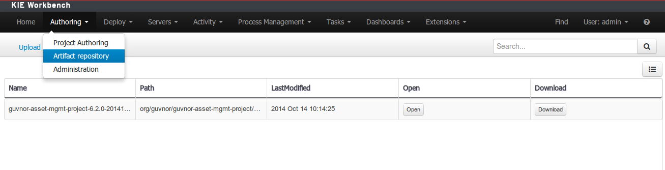
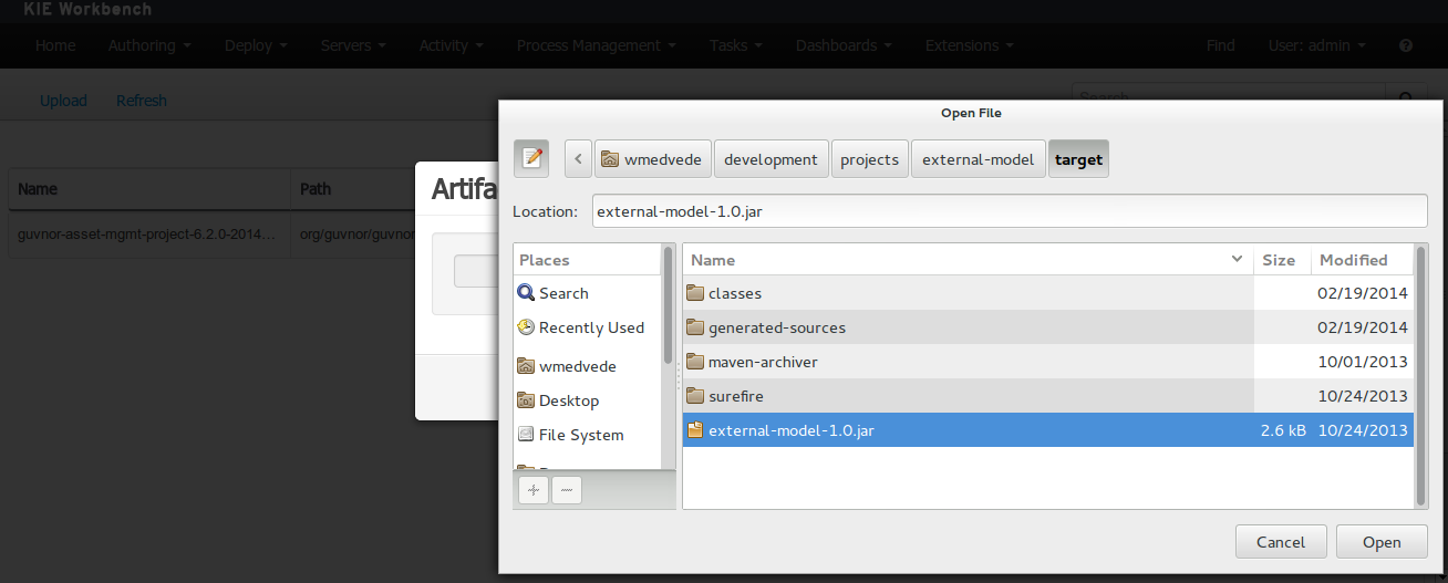
Once the file has been loaded it will be displayed in the repository files list.
If the uploaded file is not a valid Maven JAR (don’t have a pom.xml file) the system will prompt the user in order to provide a GAV for the file to be installed.
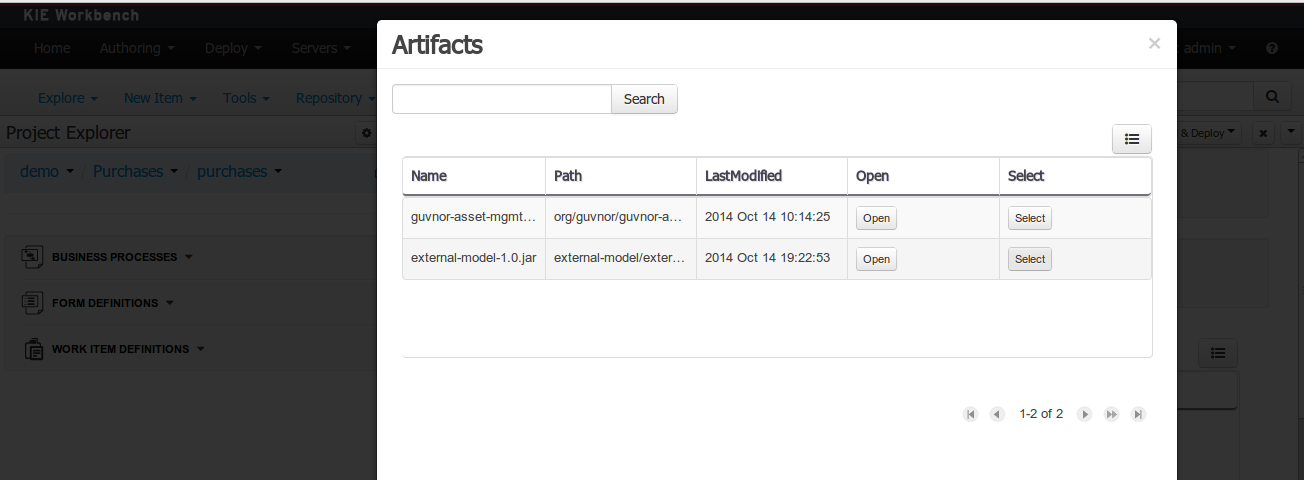
Open the project editor (see bellow) and click on the "Add from repository" button to open the JAR selector to see all the installed JAR files in current "Guvnor M2 repository". When the desired file is selected the project should be saved in order to make the new dependency available.
Using the external objects
When a dependency to an external JAR has been set, the external POJOs can be used in the context of current project data model in the following ways:
-
External POJOs can be extended by current model data objects.
-
External POJOs can be used as field types for current model data objects.
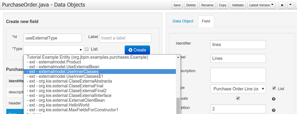
The following screenshot shows how external objects are prefixed with the string " -ext- " in order to be quickly identified.
3.7.7.7. Roundtrip and concurrency
Current version implements roundtrip and code preservation between Data modeller and Java source code. No matter where the Java code was generated (e.g. Eclipse, Data modeller), the data modeller will only create/delete/update the necessary code elements to maintain the model updated, i.e, fields, getter/setters, constructors, equals method and hashCode method. Also whatever Type or Field annotation not managed by the Data Modeler will be preserved when the Java sources are updated by the Data modeller.
Aside from code preservation, like in the other workbench editors, concurrent modification scenarios are still possible. Common scenarios are when two different users are updating the model for the same project, e.g. using the data modeller or executing a 'git push command' that modifies project sources.
From an application context’s perspective, we can basically identify two different main scenarios:
No changes have been undertaken through the application
In this scenario the application user has basically just been navigating through the data model, without making any changes to it. Meanwhile, another user modifies the data model externally.
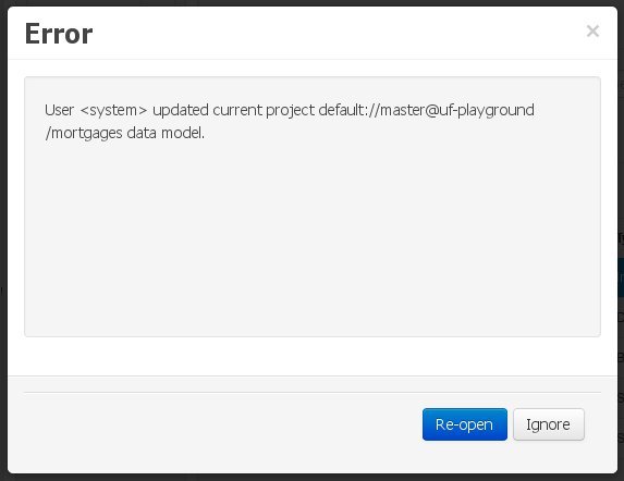
In this case, no immediate warning is issued to the application user. However, as soon as the user tries to make any kind of change, such as add or remove data objects or properties, or change any of the existing ones, the following pop-up will be shown:
The user can choose to either:
-
Re-open the data model, thus loading any external changes, and then perform the modification he was about to undertake, or
-
Ignore any external changes, and go ahead with the modification to the model. In this case, when trying to persist these changes, another pop-up warning will be shown:
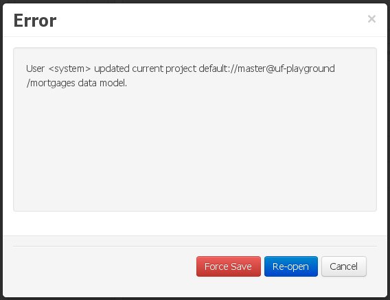 Figure 78. Force save / re-open
The "Force Save" option will effectively overwrite any external changes, while "Re-open" will discard any local changes and reload the model.
"Force Save" overwrites any external changes!
Changes have been undertaken through the application
The application user has made changes to the data model. Meanwhile, another user simultaneously modifies the data model from outside the application context.
In this alternative scenario, immediately after the external user commits his changes to the asset repository (or e.g. saves the model with the data modeller in a different session), a warning is issued to the application user:
As with the previous scenario, the user can choose to either:
-
Re-open the data model, thus losing any modifications that where made through the application, or
-
Ignore any external changes, and continue working on the model.
One of the following possibilities can now occur: ** The user tries to persist the changes he made to the model by clicking the "Save" button in the data modeller top level menu. This leads to the following warning message:
+
Figure 80. Force save / re-openThe "Force Save" option will effectively overwrite any external changes, while "Re-open" will discard any local changes and reload the model.
3.7.8. Data Sets
A data set is basically a set of columns populated with some rows, a matrix of data composed of timestamps, texts and numbers. A data set can be stored in different systems: a database, an excel file, in memory or in a lot of other different systems. On the other hand, a data set definition tells the workbench modules how such data can be accessed, read and parsed.
Notice, it’s very important to make crystal clear the difference between a data set and its definition since the workbench does not take care of storing any data, it just provides an standard way to define access to those data sets regardless where the data is stored.
Let’s take for instance the data stored in a remote database. A valid data set could be, for example, an entire database table or the result of an SQL query. In both cases, the database will return a bunch of columns and rows. Now, imagine we want to get access to such data to feed some charts in a new workbench perspective. First thing is to create and register a data set definition in order to indicate the following:
-
where the data set is stored,
-
how can be accessed, read and parsed and
-
what columns contains and of which type.
This chapter introduces the available workbench tools for registering and handling data set definitions and how this definitions can be consumed in other workbench modules like, for instance, the Perspective Editor.
|
For simplicity sake we will be using the term data set to refer to the actual data set definitions as Data set and Data set definition can be considered synonyms under the data set authoring context. |
3.7.8.1. Data Set Authoring Perspective
Everything related to the authoring of data sets can be found under the Data Set Authoring perspective which is accessible from the following top level menu entry: Extensions>Data Sets, as shown in the following screenshot.
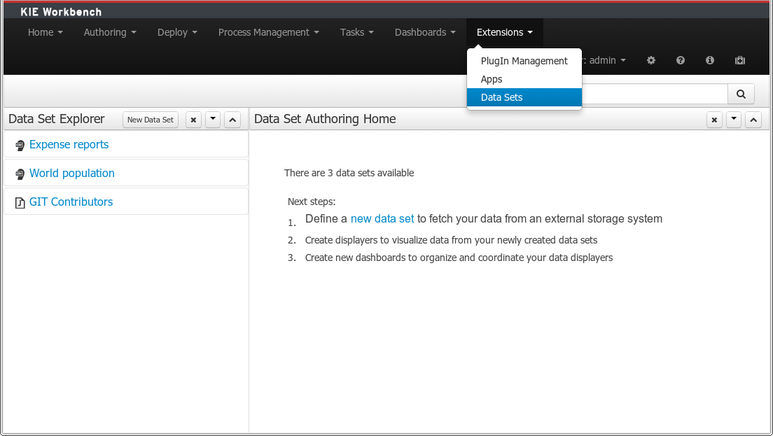
The center panel, shows a welcome screen, whilst the left panel contains the Data Set Explorer listing all the data sets available
|
This perspective is only intended to Administrator users, since defining data sets can be considered a low level task. |
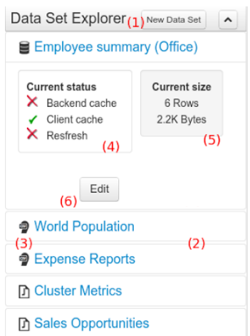
3.7.8.2. Data Set Explorer
The Data Set Explorer list the data sets present in the system. Every time the user clicks on the data set it shows a brief summary alongside the following information:
-
(1) A button for creating a new Data set
-
(2) The list of currently available Data sets
-
(3) An icon that represents the Data set’s provider type (Bean, SQL, CSV, etc)
-
(4) Details of current cache and refresh policy status
-
(5) Details of current size on backend (unit as rows) and current size on client side (unit in bytes)
-
(6) The button for editing the Data set. Once clicked the Data set editor screen is opened on the center panel
The next sections explains how to create, edit and fine tune data set definitions.
3.7.8.3. Data Set Creation
Clicking on the New Data Set button opens a new screen from which the user is able to create a new data set definition in three steps:
-
Provider type selection
Specify the kind of the remote storage system (BEAN, SQL, CSV, ElasticSearch)
-
Provider configuration
Specify the attributes for being able to look up data from the remote system. The configuration varies depending on the data provider type selected.
-
Data set columns & filter
Live data preview, column types and initial filter configuration.
Step 1: Provider type selection
Allows the user’s specify the type of data provider of the data set being created.
This screen lists all the current available data provider types and helper popovers with descriptions. Each data provider is represented with a descriptive image:
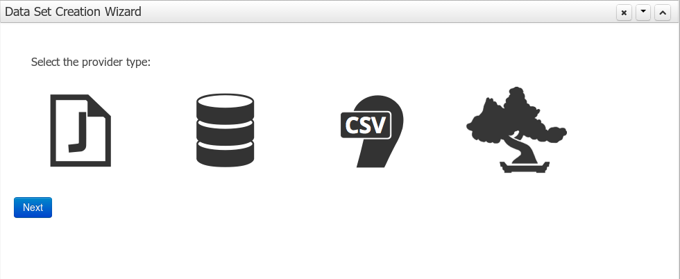
Four types are currently supported:
-
Bean (Java class) - To generate a data set directly from Java
-
SQL - For getting data from any ANSI-SQL compliant database
-
CSV - To upload the contents of a remote or local CSV file
-
Elastic Search - To query and get documents stored on Elastic Search nodes as data sets
Once a type is selected, click on Next button to continue with the next workflow step.
Step 2: Configuration
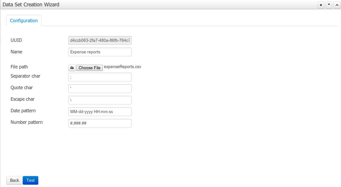
The provider type selected in the previous step will determine which configuration settings the system asks for.
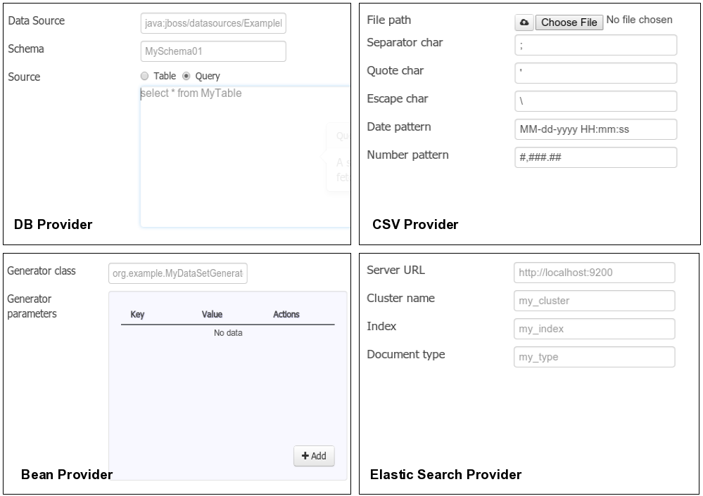
|
The UUID attribute is a read only field as it’s generated by the system. It’s only intended for usage in API calls or specific operations. |
Step 3: Data set columns and preview
After clicking on the Test button (see previous step), the system executes a data set lookup test call in order to check if the remote system is up and the data is available. If everything goes ok the user will see the following screen:
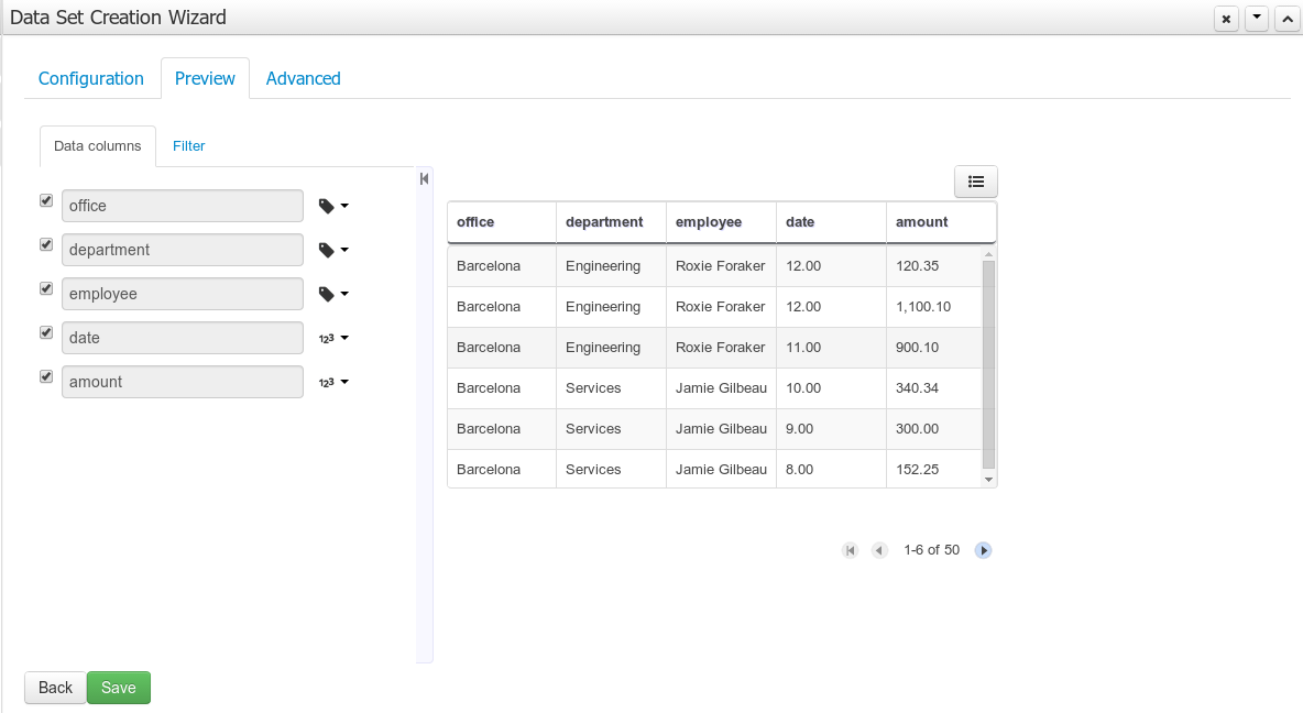
This screen shows a live data preview along with the columns the user wants to be part of the resulting data set. The user can also navigate through the data and apply some changes to the data set structure. Once finished, we can click on the Save button in order to register the new data set definition.
We can also change the configuration settings at any time just by going back to the configuration tab. We can repeat the Configuration>Test>Preview cycle as may times as needed until we consider it’s ready to be saved.
Columns
In the Columns tab area the user can select what columns are part of the resulting data set definition.
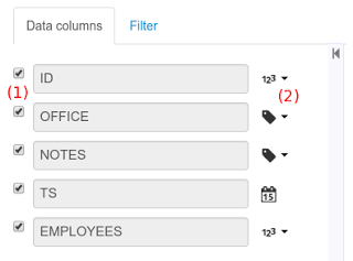
-
(1) To add or remove columns. Select only those columns you want to be part of the resulting data set
-
(2) Use the drop down image selector to change the column type
A data set may only contain columns of any of the following 4 types:
-
Label - For text values supporting group operations (similar to the SQL "group by" operator) which means you can perform data lookup calls and get one row per distinct value.
-
Text - For text values NOT supporting group operations. Typically for modeling large text columns such as abstracts, descriptions and the like.
-
Number - For numeric values. It does support aggregation functions on data lookup calls: sum, min, max, average, count, disctinct.
-
Date - For date or timestamp values. It does support time based group operations by different time intervals: minute, hour, day, month, year, …
No matter which remote system you want to retrieve data from, the resulting data set will always return a set of columns of one of the four types above. There exists, by default, a mapping between the remote system column types and the data set types. The user is able to modify the type for some columns, depending on the data provider and the column type of the remote system. The system supports the following changes to column types:
-
Label <> Text - Useful when we want to enable/disable the categorization (grouping) for the target column. For instance, imagine a database table called "document" containing a large text column called "abstract". As we do not want the system to treat such column as a "label" we might change its column type to "text". Doing so, we are optimizing the way the system handles the data set and
-
Number <> Label - Useful when we want to treat numeric columns as labels. This can be used for instance to indicate that a given numeric column is not a numeric value that can be used in aggregation functions. Despite its values are stored as numbers we want to handle the column as a "label". One example of such columns are: an item’s code, an appraisal id., …
|
BEAN data sets do not support changing column types as it’s up to the developer to decide which are the concrete types for each column. |
Filter
A data set definition may define a filter. The goal of the filter is to leave out rows the user does not consider necessary. The filter feature works on any data provider type and it lets the user to apply filter operations on any of the data set columns available.
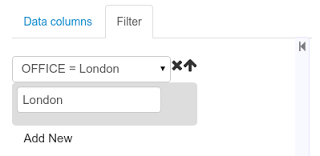
While adding or removing filter conditions and operations, the preview table on central area is updated with live data that reflects the current filter status.
There exists two strategies for filtering data sets and it’s also important to note that choosing between the two have important implications. Imagine a dashboard with some charts feeding from a expense reports data set where such data set is built on top of an SQL table. Imagine also we only want to retrieve the expense reports from the "London" office. You may define a data set containing the filter "office=London" and then having several charts feeding from such data set. This is the recommended approach. Another option is to define a data set with no initial filter and then let the individual charts to specify their own filter. It’s up to the user to decide on the best approach.
Depending on the case it might be better to define the filter at a data set level for reusing across other modules. The decision may also have impact on the performance since a filtered cached data set will have far better performance than a lot of individual non-cached data set lookup requests. (See the next section for more information about caching data sets).
|
Notice, for SQL data sets, the user can use both the filter feature introduced or, alternatively, just add custom filter criteria to the SQL sentence. Although, the first approach is more appropriated for non technical users since they might not have the required SQL language skills. |
3.7.8.4. Data set editor
To edit an existing data set definition go the data set explorer, expand the desired data set definition and click on the Edit button. This will cause a new editor panel to be opened and placed on the center of the screen, as shown in the next screenshot:
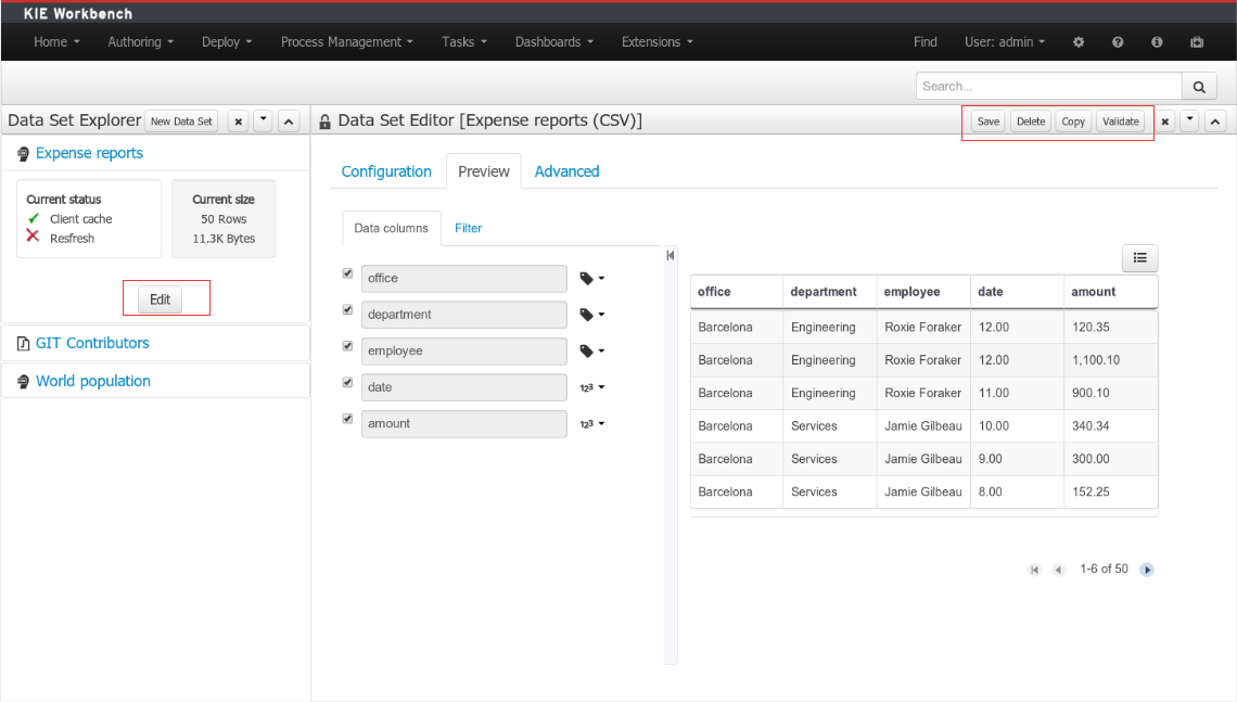
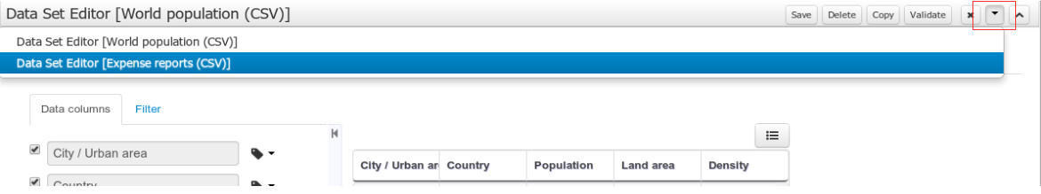
-
Save - To validate the current changes and store the data set definition.
-
Delete - To remove permanently from storage the data set definition. Any client module referencing the data set may be affected.
-
Validate - To check that all the required parameters exists and are correct, as well as to validate the data set can be retrieved with no issues.
-
Copy - To create a brand new definition as a copy of the current one.
|
Data set definitions are stored in the underlying GIT repository as JSON files. Any action performed is registered in the repository logs so it is possible to audit the change log later on. |
3.7.8.5. Advanced settings
In the Advanced settings tab area the user can specify caching and refresh settings. Those are very important for making the most of the system capabilities thus improving the performance and having better application responsive levels.
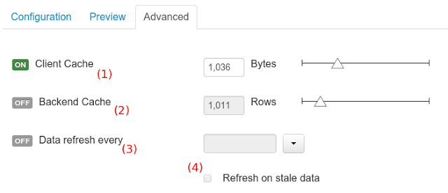
-
(1) To enable or disable the client cache and specify the maximum size (bytes).
-
(2) To enable or disable the backend cache and specify the maximum cache size (number of rows).
-
(3) To enable or disable automatic refresh for the Data set and the refresh period.
-
(4) To enable or disable the refresh on stale data setting.
Let’s dig into more details about the meaning of these settings.
3.7.8.6. Caching
The system provides caching mechanisms out-of-the-box for holding data sets and performing data operations using in-memory strategies. The use of these features brings a lot of advantages, like reducing the network traffic, remote system payload, processing times etc. On the other hand, it’s up to the user to fine tune properly the caching settings to avoid hitting performance issues.
Two cache levels are supported:
-
Client level
-
Backend level
The following diagram shows how caching is involved in any data set operation:
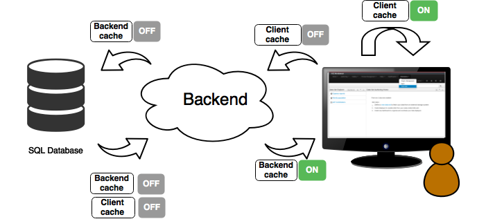
Any data look up call produces a resulting data set, so the use of the caching techniques determines where the data lookup calls are executed and where the resulting data set is located.
Client cache
If ON then the data set involved in a look up operation is pushed into the web browser so that all the components that feed from this data set do not need to perform any requests to the backend since data set operations are resolved at a client side:
-
The data set is stored in the web browser’s memory
-
The client components feed from the data set stored in the browser
-
Data set operations (grouping, aggregations, filters and sort) are processed within the web browser, by means of a Javascript data set operation engine.
If you know beforehand that your data set will remain small, you can enable the client cache. It will reduce the number of backend requests, including the requests to the storage system. On the other hand, if you consider that your data set will be quite big, disable the client cache so as to not hitting with browser issues such as slow performance or intermittent hangs.
Backend cache
Its goal is to provide a caching mechanism for data sets on backend side.
This feature allows to reduce the number of requests to the remote storage system , by holding the data set in memory and performing group, filter and sort operations using the in-memory engine.
It’s useful for data sets that do not change very often and their size can be considered acceptable to be held and processed in memory. It can be also helpful on low latency connectivity issues with the remote storage. On the other hand, if your data set is going to be updated frequently, it’s better to disable the backend cache and perform the requests to the remote storage on each look up request, so the storage system is in charge of resolving the data set lookup request.
|
BEAN and CSV data providers relies by default on the backend cache, as in both cases the data set must be always loaded into memory in order to resolve any data lookup operation using the in-memory engine. This is the reason why the backend settings are not visible in the Advanced settings tab. |
3.7.8.7. Refresh
The refresh feature allows for the invalidation of any cached data when certain conditions are meet.
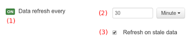
-
(1) To enable or disable the refresh feature.
-
(2) To specify the refresh interval.
-
(3) To enable or disable data set invalidation when the data is outdated.
The data set refresh policy is tightly related to data set caching, detailed in previous section. This invalidation mechanism determines the cache life-cycle.
Depending on the nature of the data there exist three main use cases:
-
Source data changes predictable - Imagine a database being updated every night. In that case, the suggested configuration is to use a "refresh interval = 1 day" and disable "refresh on stale data". That way, the system will always invalidate the cached data set every day. This is the right configuration when we know in advance that the data is going to change.
-
Source data changes unpredictable - On the other hand, if we do not know whether the database is updated every day, the suggested configuration is to use a "refresh interval = 1 day" and enable "refresh on stale data". If so the system, before invalidating any data, will check for modifications. On data modifications, the system will invalidate the current stale data set so that the cache is populated with fresh data on the next data set lookup call.
-
Real time scenarios - In real time scenarios caching makes no sense as data is going to be updated constantly. In this kind of scenarios the data sent to the client has to be constantly updated, so rather than enabling the refresh settings (remember this settings affect the caching, and caching is not enabled) it’s up to the clients consuming the data set to decide when to refresh. When the client is a dashboard then it’s just a matter of modifying the refresh settings in the Displayer Editor configuration screen and set a proper refresh period, "refresh interval = 1 second" for example.
3.7.9. Data Source Management
The data source management system provides the ability of defining data sources for accessing external databases. This data sources can be later used by other workbench components like the Data Sets.
3.7.9.1. Database Drivers
To be able to communicate with the target database a data source will need a database driver to access it. This is why the system additionally provides the ability of defining database drivers for the data sources operation. A database driver is basically a JDBC compliant driver. We will see them in the next topics.
3.7.9.2. Data Source Authoring Perspective
Everything related to the authoring of data sources and drivers can be found under the Data Source Authoring perspective accessible from the following top level menu entry: Extensions>Data Sources, as shown in the following screenshot.
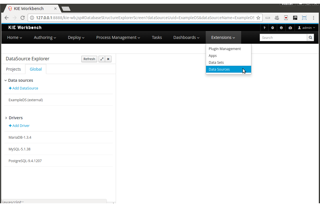
|
This perspective is only intended for Administrator users, since defining data sources can be considered a low level task. |
3.7.9.3. Data Source Explorer
The Data Source Explorer lists the data sources and drivers currently defined in the system, at the same time it provides the required actions for managing them.

-
(1) Action link for creating a new data source
-
(2) List of currently available data sources
-
(3) Action link for creating a new driver
-
(4) List of currently available drivers
3.7.9.4. New Data Source Wizard
Clicking on the New Data Source action link opens the New Data Source Wizard:
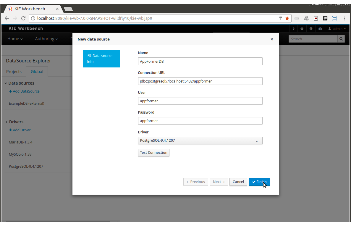
The following required parameters define a data source:
-
Name: A unique name for the data source definition.
-
Connection URL: A JDBC database connection url compliant with the selected driver type. This is an example of a connection url for a PostgreSQL database: jdbc:postgresql://localhost:5432/appformer.
-
User: A user name in the target database.
-
Password: The corresponding user password.
-
Driver: Selects the JDBC driver to be used for connecting to the target database. Note that the connection url format may vary depending on the driver, and different database vendors typically provides different drivers.
-
Test connection: Once clicked, the system will show a dialog similar to the one below showing the connection test status.
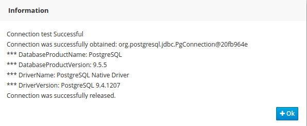
|
While not required, it’s recommended to use the test connection button to check the correctness of the data source parameters prior to finishing the data source creation. |
3.7.9.5. Data Source Editor
The Data Source Editor is opened by clicking on a data source item in the Data Source Explorer.
The following screenshot shows the Data Source Editor opened for the data source of the example above.
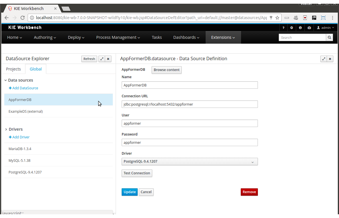
-
Main Panel: The main panel basically lets you modify the data source configuration parameters.
-
Test connection: Tests the connection.
|
It’s a recommended practice to test the connection prior saving a modified data source. |
3.7.9.6. Data Source Content Browser
The data source content browser is opened by clicking on the Browse Content button, and enables the navigation through the database structure pointed by the data source. The navigation is performed in three levels, Schemas level, Current schema level and Current table level.
-
Schemas level: lists all the database schemas accessible by current data source. Which schemas are listed depends on the database access rights granted to the user which was used in the connection configuration. Similarly for the following item.
-
Current schema level: shows all the database tables for the selected schema.
-
Current table level: shows the table content for the selected table.
The following screenshots show the information shown at each level, for a user that realized the following navigation steps. Selects the "public" schema → Selects the "country" table.
Schema Selection:
Clicking on the Open button opens the Current schema level for the selected schema.
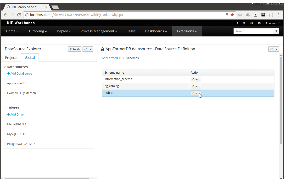
Table Selection:
Clicking on the Open button opens the Current table level for the selected table.
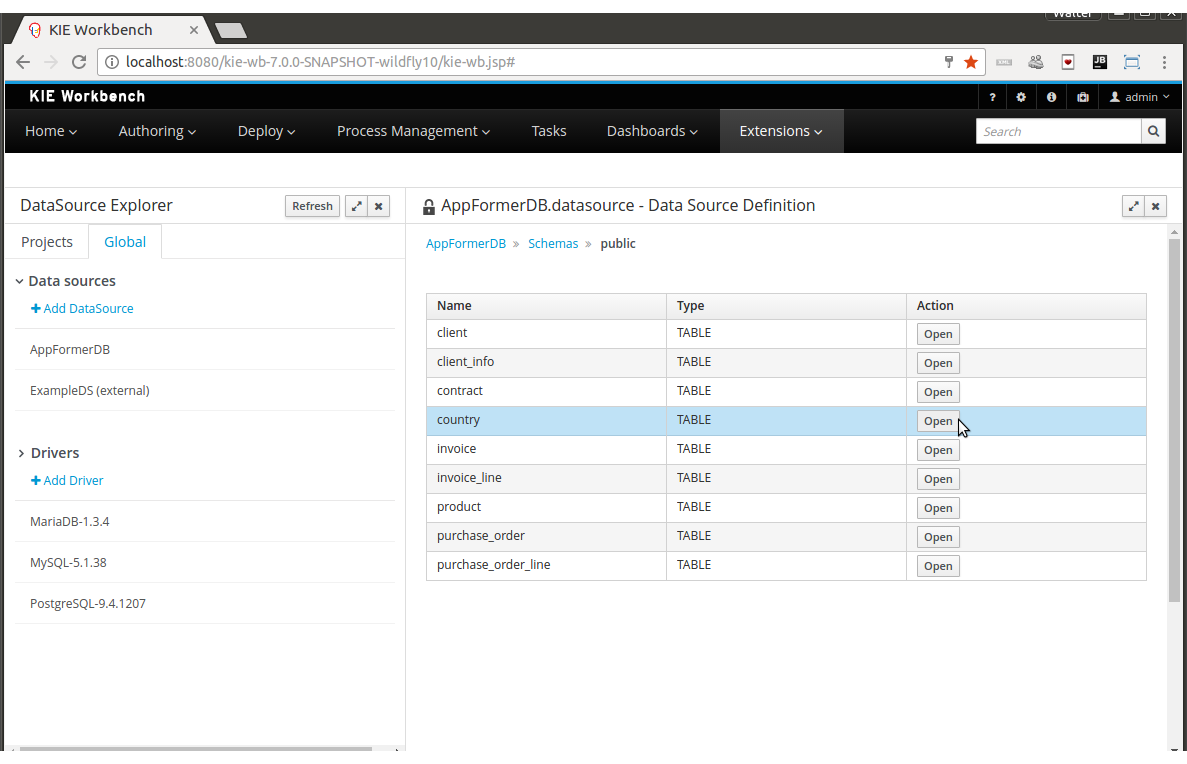
Table information:
The rows for the selected table are shown at this level.
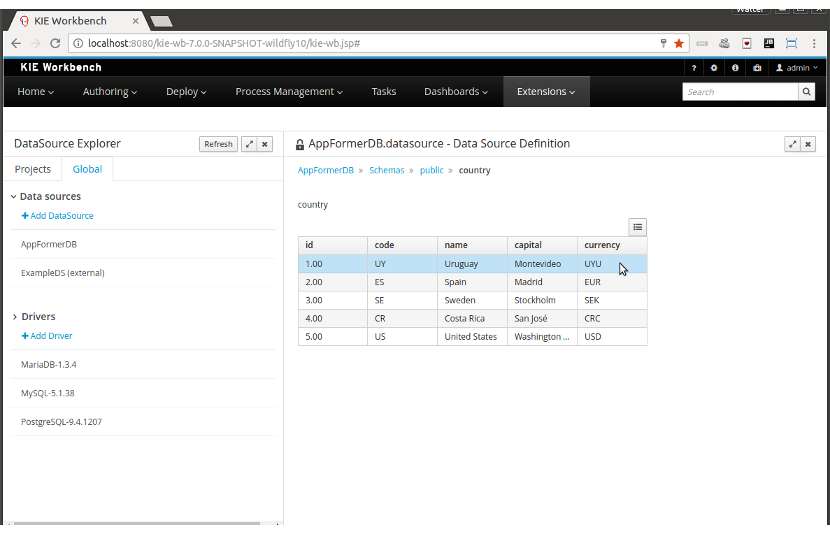
3.7.9.7. External Data Sources
External data sources are typically not defined in current workbench, instead they exist in current container and for some containers like Wildfly 10 or the JBoss EAP 7 servers they can still be listed in read only mode. In this cases only the Data Source Content Browser is enabled.
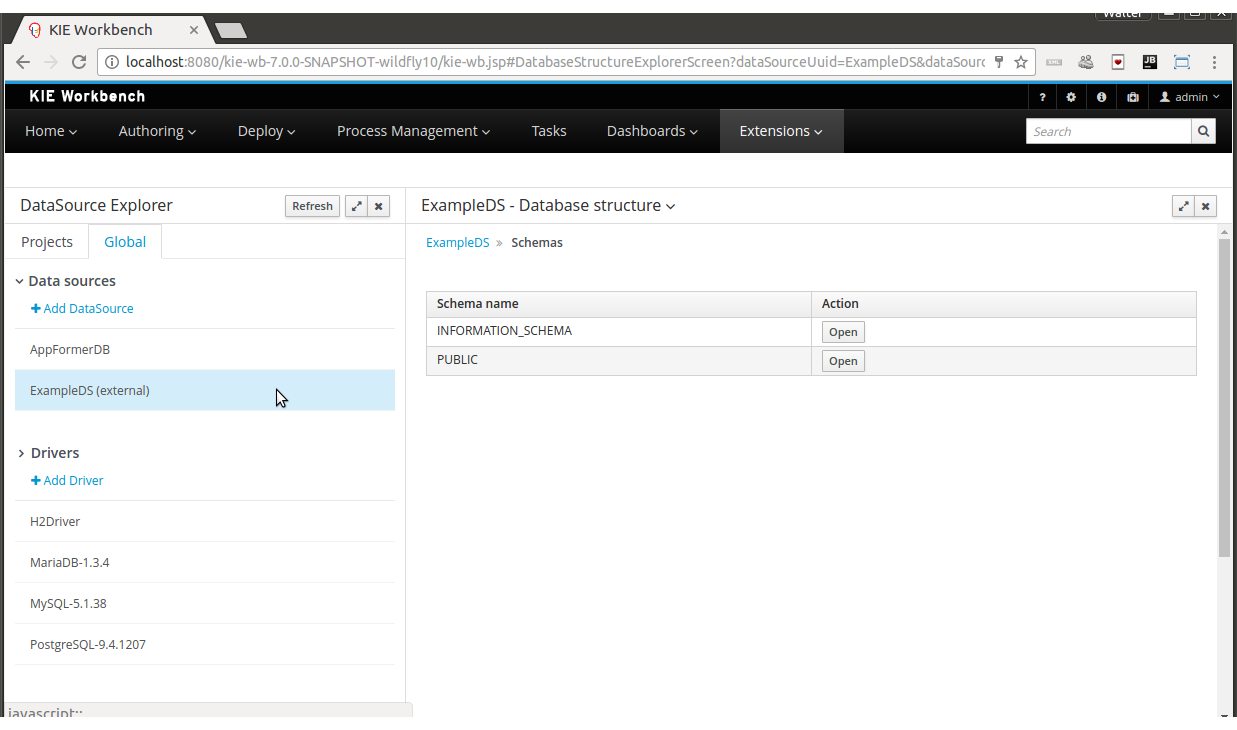
3.7.9.8. New Driver Wizard
Clicking on the New Driver action link opens the New Driver Wizard:
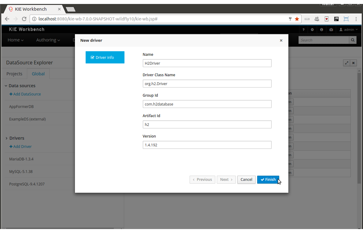
The following required parameters define a Driver:
-
Name: A unique name for the driver definition.
-
Driver Class Name: The java fully qualified name for the class that implements the JDBC driver contract.
-
Group Id: The maven group id for the artifact that contains the JDBC driver implementation.
-
Artifact Id: The maven artifact id for the artifact that contains the JDBC driver implementation.
-
Version: The maven version for the artifact that contains the JDBC driver implementation.
|
Some commercial database drivers (like Oracle) are not available in the maven central repository. You can use those by first uploading them via Artifact Repository perspective and then continue with the driver configuration as for the drivers available in the maven central repository. |
3.7.9.9. Driver Editor
The Driver Editor is opened by clicking on a driver item in the Data Source Explorer.
The following screenshot shows the Driver Editor opened for the driver of the example above.
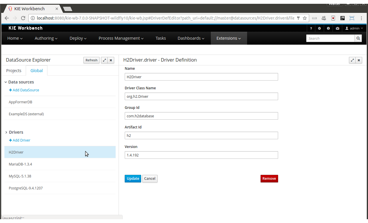
-
Main Panel: The main panel basically lets you modify the driver configuration parameters. See New Driver Wizard.
3.7.9.10. By Default Drivers
The system is shipped with a set of by default configured drivers for the most common used open source databases. And they are aligned with the latest database versions supported by the Wildfly 10 and the JBoss EAP 7 servers.
3.8. Security management
This section describes how administrator users can manage the application’s users, groups and permissions using an intuitive and friendly user interface in order to configure who can access the different resources and features available.
3.8.1. Basic concepts
In order to understand the security management features provided, a few core concepts need to be introduced first.
3.8.1.1. Roles vs Groups
Users can be assigned with more than one role and/or group. It is always mandatory to assign at least one role to the user, otherwise he/she won’t be able to login. Roles are defined at application server level and they are part of the webapp’s web.xml descriptor. On the other hand, groups are a more flexible concept, since they can be defined at runtime.
3.8.1.2. Permissions
A permission is basically something the user can do within the application. Usually, an action related to a specific resource. For instance:
-
View a perspective
-
Save a project
-
View a repository
-
Delete a dashboard
A permission can be granted or denied and it can be global or resource specific. For instance:
-
Global: “Create new perspectives”
-
Specific: “View the home perspective”
As you can see, a permission is a resource + action pair. In the concrete case of a perspective we have: read, update, delete and create as the available actions. That means that there are four possible permissions that could be granted for perspectives.
Permissions do not necessarily need to be tied to a resource. Sometimes it is also neccessary to protect access to specific features, like for instance "generate a sales report". That means, permissions can be used not only to protect access to resources but also to custom features within the application.
3.8.1.3. Authorization policy
The set of permissions assigned to every role and/or group is called the authorization (or security) policy. Every application contains a single security policy which is used every time the system checks a permission.
The authorization policy file is stored in a file called WEB-INF/classes/security-policy.properties under the application’s WAR structure.
| If no policy is defined then the authorization management features are disabled and the application behaves as if all the resources & features were granted by default. |
Here is an example of a security policy file:
# Role "admin"
role.admin.permission.perspective.read=true
role.admin.permission.perspective.read.Dashboard=false

# Role "user"
role.user.permission.perspective.read=false
role.user.permission.perspective.read.Home=true
role.user.permission.perspective.read.Dashboard=true
Every entry defines a single permission which is assigned to a role/group. On application start up, the policy file is loaded and stored into memory.
3.8.1.4. Security provider
A security environment is usually provided by the use of a realm. Realms are used to restrict access to the different application’s resources. So realms contains the information about the users, groups, roles, permissions and any other related information.
In most typical scenarios the application’s security is delegated to the container’s security mechanism, which consumes a given realm at same time. It’s important to consider that there exist several realm implementations, for example Wildfly provides a realm based on the application-users.properties/application-roles.properties files, Tomcat provides a realm based on the tomcat-users.xml file, etc. So there is no single security realm to rely on, it can be different in each installation.
Due to the potential different security environments that have to be supported, the security module provides a well defined API with some default built-in security providers. A security provider is the formal name given to a concrete user and group management service implementation for a given realm.
The user & group management features available will depend on the security provider configured. If the built-in providers do not fit with the application’s security realm, it is easy to build and register your own provider.
3.8.2. Installation and setup
At the time of this writing, the application provides two pre-installed security providers:
-
Wildfly 10 / EAP 7 distribution - Both distributions use the Wildfly security provider configured for the use of the default realm files application-users.properties and application-roles.properties
-
Tomcat distribution - It uses the Tomcat security provider configured for the use of the default realm file tomcat-users.xml
Please read each provider’s documentation in order to apply the concrete settings for the target deployment environment.
On the other hand, when either using a custom security provider or using one of the availables, consider the following installation options:
-
Enable the security management feature on an existing WAR distribution
-
Setup and installation in an existing or new project
NOTE: If no security provider is installed, there will be no available user interface for managing the security realm. Once a security provider is installed and setup, the user and group management features are automatically enabled in the security management UI (see the Usage section below).
3.8.2.1. Enabling user & group management
Given an existing WAR distribution, follow these steps in order to install and enable the user & group management features:
-
Ensure the following libraries are present on WEB-INF/lib:
-
WEB-INF/lib/uberfire-security-management-api-?.jar
-
WEB-INF/lib/uberfire-security-management-backend-?.jar
-
-
Copy the the security provider library to WEB-INF/lib:
-
Eg: WEB-INF/lib/uberfire-security-management-wildfly-?.jar
-
If the provider requires additional libraries, copy them as well (read each provider’s documentation for more information).
-
-
Replace the whole content of the WEB-INF/classes/security-management.properties file, or if not present, create it. The settings present on this file depend on the concrete implementation used. Please read each provider’s documentation for more information.
-
If deploying on Wildfly or EAP, check if the WEB-INF/jboss-deployment-structure.xml requires any update (read each provider’s documentation for more information).
3.8.2.2. Disabling user & group management
The user & groups management features can be disabled, and thus no services or user interface will be available, by means of either:
-
Uninstalling the security provider from the application
When no concrete security provider is installed, the user and group management features will be disabled and no services or user interface will be displayed to the user. This is the case for instance, in Weblogic and Websphere installations as there is no a security provider implementation available at the time of this writing.
-
Removing or commenting the security management configuration file
Removing or commenting all the lines in the configuration file located at WEB-INF/classes/security-management.properties is another way to disable the user and group management features.
3.8.2.3. Upgrading an existing installation
In versions prior to 7, the only way to grant access to resources like Organizational Units, Repositories or Projects was to indicate which roles were able to access a given instance. Those roles were stored in GIT as part of the instance persistent status. The CLI was the tool used to add/remove roles:
-
remove-role-repo: remove role(s) from repository
-
add-role-org-unit: add role(s) to organizational unit
-
remove-role-org-unit: remove role(s) from organizational unit
-
add-role-project: add role(s) to project
-
remove-role-project: remove role(s) from project
As of version 7, the authorization policy is based on permissions. That means is no longer required to keep a list of roles per resource instance. What is required is to define proper permission entries into the active authorization policy using the security management UI (see the Usage section below).
The commands above are no longer required so they have been removed. Basically, what those commands did is to set what roles were able to read a specific item.
In order to guarantee backward compatibility with versions prior to 7, an automatic migration tool is bundled within the application, which converts the list of roles assigned to any organizational unit, repository or project into read permission entries of the security policy.
This tool is executed when the application start ups for the first time, during the security policy deployment. So existing customers, do not have to worry about it, as they will keep their security settings.
3.8.3. Usage
The Security Management perspective is available under the Home section in the top menu bar.
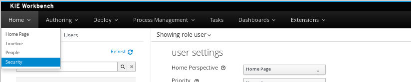
The next screenshot shows how this new perspective looks:
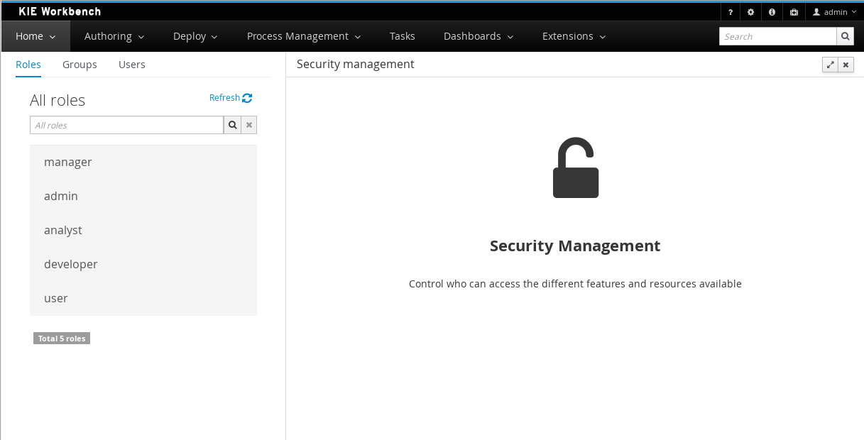
This perspective supports:
-
List all the roles, groups and users available
-
Create & delete users and groups
-
Edit users, assign roles or groups, and change user properties
-
Edit both roles & groups security settings, which include:
-
The home perspective a user will be directed to after login
-
The permissions granted or denied to the different workbench resources and features available
-
All of the above together provides a complete users and groups management subsystem as well as a permission configuration UI for protecting access to specific resources or features.
The next sections provide a deep insight into all these features.
| The user and group management related features can be entirely disabled. See the previous section Disabling user & group management. If that’s the case then both the Groups and _Users tabs will remain hidden from the user. |
3.8.3.1. User management
By selecting the Users tab in the left sidebar, the application shows all the users present by default on the application’s security realm:
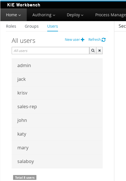
-
Searching for users
In addition to listing all the users, search is also allowed:
+ When specifying the search pattern in the search box the users listed will be reduced to only those that matches the search pattern.
+
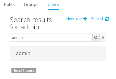
+ Search patterns depend on the concrete security provider being used by the application. Please read each provider’s documentation for more information.
-
Creating new users
By clicking on the "New user +" anchor, a form is displayed on the screen’s right.
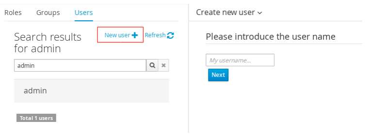
This is a wizard like interface where the application asks for the new user name, a password as well as what roles/groups to assign.
-
Editing a user
After clicking on a user in the left sidebar, the user editor is opened on the screen’s right.
For instance, the details screen for the admin user when using the Wildfly security provider looks like the following screenshot:
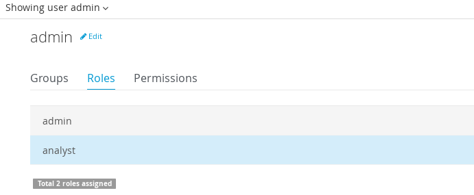
Same screen but when using the Keycloak security provider looks as:
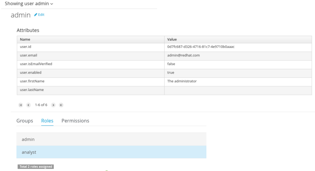
Note that when using the Keycloak provider, a new user attributes section is displayed, but it’s not present when using the Wildfly provider. This is due to the fact that the information and actions available always depend on each provider’s capabilities as explained in the Security provider capabilities section below.
Next is the type of information handled in the user’s details screen:
-
The user name
-
The user’s attributes
-
The assigned groups
-
The assigned roles
-
The permissions granted or denied
In order to update or delete an existing user, click on the Edit button present near to the username in the user editor screen:
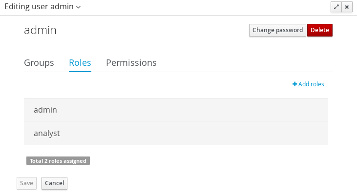
Once the editor is in edit mode, different operations can be done (provided the security provider supports them):
For instance, to modify the set of roles and groups assigned to the user or to change the user’s password as well.
-
Permissions summary
The Permissions tab shows a summary of all the permissions assigned to this particular user. This is a very helpful view as it allows administrator users to verify if a target user has the right permission levels according to the security settings of its roles and groups.
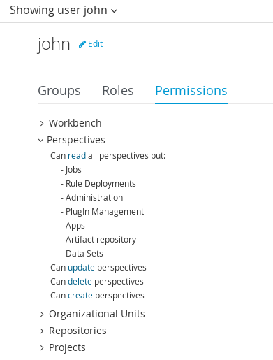
Further details about how to assign permissions to roles and groups are in the Security Settings Editor section below.
-
Updating the user’s attributes
User attributes can added or deleted using the actions available in the attributes table:
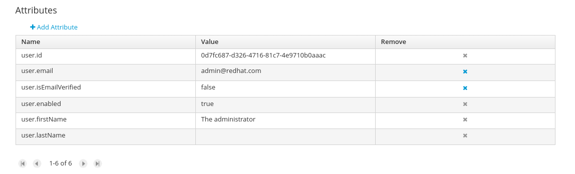
-
Updating assigned groups
From the Groups tab, a group selection popup is presented when clicking on the Add to groups button:

This popup screen allows the user to search and select or deselect the groups assigned to the user.
-
Updating assigned roles
From the Roles tab, a role selection popup is presented when clicking on Add to roles button:
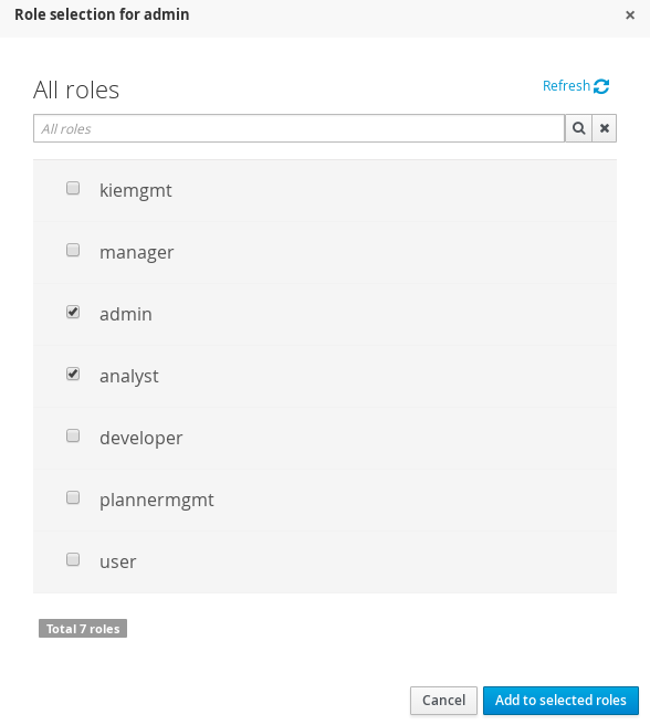
This popup screen allows the user to search and select or deselect the roles assigned to the user.
-
Changing the user’s password
A change password popup screen is presented when clicking on the Change password button:
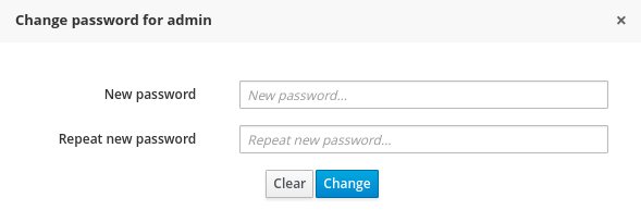
-
Deleting users
The user currently being edited can be deleted from the realm by clicking on the Delete button.
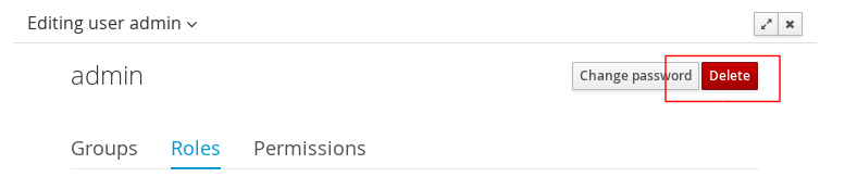
Security provider capabilities
Each security realm can provide support for different operations. For example consider the use of a Wildfly’s realm based on properties files. The contents for the applications-users.properties is like:
admin=207b6e0cc556d7084b5e2db7d822555c
salaboy=d4af256e7007fea2e581d539e05edd1b
maciej=3c8609f5e0c908a8c361ca633ed23844
kris=0bfd0f47d4817f2557c91cbab38bb92d
katy=fd37b5d0b82ce027bfad677a54fbccee
john=afda4373c6021f3f5841cd6c0a027244
jack=984ba30e11dda7b9ed86ba7b73d01481
director=6b7f87a92b62bedd0a5a94c98bd83e21
user=c5568adea472163dfc00c19c6348a665
guest=b5d048a237bfd2874b6928e1f37ee15e
kiewb=78541b7b451d8012223f29ba5141bcc2
kieserver=16c6511893651c9b4b57e0c027a96075
Notice that it’s based on key-value pairs where the key is the username, and the value is the hashed value for the user’s password. So a user is just represented by a key and its username, it does not have a name nor an address or any other meta information.
On the other hand, consider the use of a realm provided by a Keycloak server. The user information is composed by more meta-data, such as the surname, address, etc, as in the following image:
So the different services and client side components from the User and Group Management API are based on capabilities. Capabilities are used to expose or restrict the available functionality provided by the different services and client side components. Examples of capabilities are:
-
Create a user
-
Update a user
-
Delete a user
-
Update user’s attributes
-
Create a group
-
Update a group
-
Assign groups to a user
-
Assign roles to a user
Each security provider must specify a set of capabilities supported. From the previous examples, it is noted that the Wildfly security provider does not support the attributes management capability - the user is only composed by the user name. On the other hand the Keycloak provider does support this capability.
The different views and user interface components rely on the capabilities supported by each provider, so if a capability is not supported by the provider in use, the UI does not provide the views for the management of that capability. As an example, consider that a concrete provider does not support deleting users - the delete user button on the user interface will be not available.
Please take a look at the concrete service provider documentation to check all the supported capabilities for each one, the default ones can be found here.
3.8.3.2. Group management
By selecting the Groups tab in the left sidebar, the application shows all the groups present by default on the application’s security realm:
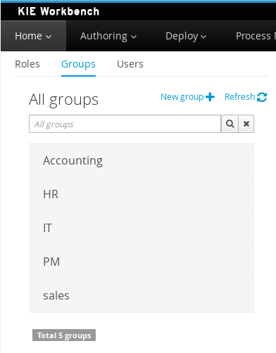
-
Searching for groups
In addition to listing all the groups, search is also allowed:
+ When specifying the search pattern in the search box the groups listed will be reduced to only those that matches the search pattern.
+
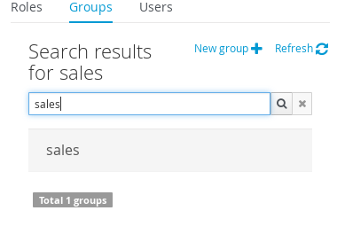
+ Search patterns depend on the concrete security provider being used by the application. Please read each provider’s documentation for more information.
-
Creating new groups
By clicking on the "New group +" anchor, a new screen will be presented on the center panel to perform a new group creation.
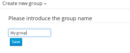
After typing a name anc clicking Save, the next step is to assign users to it:
+
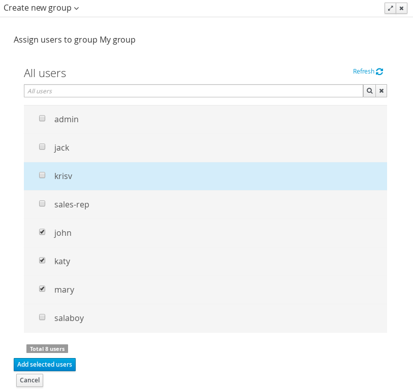
+ Clicking on the "Add selected users" button finishes the group creation.
-
Modifying a group
After clicking on a group in the left sidebar, the security settings editor for the selected group instance is opened on the screen’s right. Further details at the Security Settings Editor section.
-
Deleting groups
To delete an existing group just click on the Delete button.
3.8.3.3. Role management
By selecting the Roles tab in the left sidebar, the application shows all the application roles:
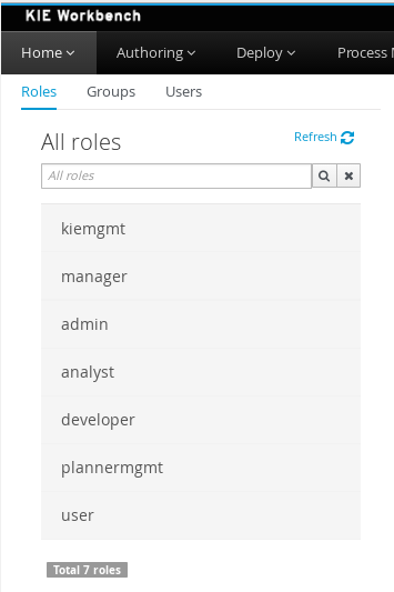
Unlike users and groups, roles can not be created nor deleted as they come from the application’s web.xml descriptor. After clicking on a role in the left sidebar, the role editor is opened on the screen’s right, which is exactly the same security settings editor used for groups. Further details at the Security Settings Editor section.
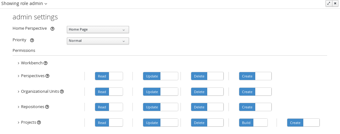
That means both role and group based permissions can be defined. The main diference between roles and group are:
-
Roles are an application defined resource. They are defined as <security-role> entries in the application’s web.xml descriptor.
-
Groups are dynamic and can be defined at runtime. The installed security provider determines where groups instances are stored.
They can be used together without any trouble. Groups are recommended though as they are a more flexible than roles.
-
Searching for roles
In addition to listing all the roles, search is also allowed:
+ When specifying the search pattern in the search box the roles listed will be reduced to only those that matches the search pattern.
+
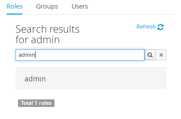
+ Search patterns depend on the concrete security provider being used by the application. Please read each provider’s documentation for more information.
3.8.4. Security Settings Editor
This editor is used to set several security settings for both roles and groups.
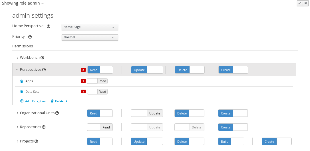
+
3.8.4.1. Home perspective
This is the perspective where the user is directed after login. This makes it possible to have different home pages for different users, since users can be assigned to different roles or groups.
3.8.4.2. Priority
It is used to determine what settings (home perspective, permissions, …) have precedence for those users with more that one role or group assigned.
Without this setting, it won’t be possible to determine what role/group should take precedence. For instance, an administrative role has higher priority than a non-administrative one. For users with both administrative and non-administrative roles granted, administrative privileges will always win, provided the administrative role’s priority is greater than the other.
3.8.4.3. Permissions
Currently, the workbench support the following permission categories.
-
Workbench: General workbench permissions, not tied to any specific resource type.
-
Perspectives: If access to a perspective is denied then it will not be shown in any of application menus. Update, Delete and Create permissions change the behaviour of the perspective management plugin editor.
-
Organizational Units: Sets who can Create, Update or Delete organizational units from the Organizational Unit section at the Administration perspective. Sets also what organizational units are visible in the Project Explorer at the Project Authoring perspective.
-
Repositories: Sets who can Create, Update or Delete repositories from the Repositories section at the Administration perspective. Sets also what repositories are visible in the Project Explorer at the Project Authoring perspective.
-
Projects: In the Project Authoring perspective, sets who can Create, Update, Delete or Build projects from the Project Editor screen as well as what projects are visible in the Project Explorer.
For perspectives, organizational units, repositories and projects it is possible to define global permissions and add single instance exceptions afterwards. For instance, Read access can be granted to all the perspectives and deny access just to an individual perspective. This is called the grant all deny a few strategy.
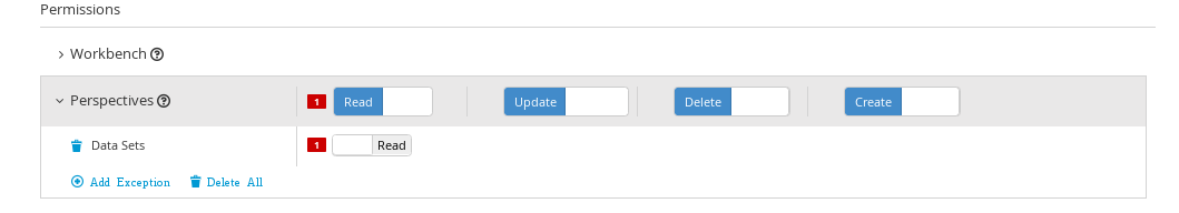
The opposite, deny all grant a few strategy is also supported:
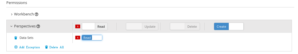
| In the example above, the Update and Delete permissions are disabled as it does not makes sense to define such permissions if the user is not even able to read perspectives. |
3.8.5. Security Policy Storage
The security policy is stored under the workbench’s VFS. Most concrete, in a GIT repo called “security”. The ACL table is stored in a file called “security-policy.properties” under the “authz” directory. Next is an example of the entries this file contains:
role.admin.home=HomePerspective
role.admin.priority=0
role.admin.permission.perspective.read=true
role.admin.permission.perspective.create=true
role.admin.permission.perspective.delete=true
role.admin.permission.perspective.update=true
Every time the ACL is modified from the security settings UI the changes are stored into the GIT repo.
Initially, when the application is deployed for the first time there is no security policy stored in GIT. However, the application might need to set-up a default policy with the different access profiles for each of the application roles.
In order to support default policies the system allows for declaring a security policy as part of the webapp’s content. This can be done just by placing a security-policy.properties file under the webapp’s resource classpath (the WEB-INF/classes directory inside the WAR archive is a valid one). On app start-up the following steps are executed:
-
Check if an active policy is already stored in GIT
-
If not, then check if a policy has been defined under the webapp’s classpath
-
If found, such policy is stored under GIT
The above is an auto-deploy mechanism which is used in the workbench to set-up its default security policy.
One slight variation of the deployment process is the ability to split the “security-policy.properties” file into small pieces so that it is possible, for example, to define one file per role. The split files must start by the “security-module-” prefix, for instance: “security-module-admin.properties”. The deployment mechanism will read and deploy both the "security-policy.properties" and all the optional “security-module-?.properties” found on the classpath.
Notice, despite using the split approach, the “security-policy.properties” must always be present as it is used as a marker file by the security subsystem in order to locate the other policy files. This split mechanism allows for a better organization of the whole security policy.
3.9. Embedding Workbench In Your Application
As we already know, Workbench provides a set of editors to author assets in different formats. According to asset’s format a specialized editor is used.
One additional feature provided by Workbench is the ability to embed it in your own (Web) Applications thru it’s standalone mode. So, if you want to edit rules, processes, decision tables, etc… in your own applications without switch to Workbench, you can.
In order to embed Workbench in your application all you’ll need is the Workbench application deployed and running in a web/application server and, from within your own web applications, an iframe with proper HTTP query parameters as described in the following table.
| Parameter Name | Explanation | Allow multiple values | Example |
|---|---|---|---|
standalone |
With just the presence of this parameter workbench will switch to standalone mode. |
no |
(none) |
path |
Path to the asset to be edited. Note that asset should already exists. |
no |
git://master@uf-playground/todo.md |
perspective |
Reference to an existing perspective name. |
no |
org.guvnor.m2repo.client.perspectives.GuvnorM2RepoPerspective |
header |
Defines the name of the header that should be displayed (useful for context menu headers). |
yes |
ComplementNavArea |
|
Path and Perspective parameters are mutual exclusive, so can’t be used together. |
3.10. Asset Management
3.10.1. Asset Management Overview
This section of the documentation describes the main features included that contribute to the Asset Management functionality provided in the KIE Workbench and KIE Drools Workbench. All the features described here are entirely optional, but the usage is recommended if you are planning to have multiple projects. All the Asset Management features try to impose good practices on the repository structure that will make the maintainace, versioning and distribution of the projects simple and based on standards. All the Asset Management features are implemented using jBPM Business Processes, which means that the logic can be reused for external applications as well as adapted for domain specific requirements when needed.
|
You must set the "kiemgmt" role to your user to be able to use the Asset Management Features |
3.10.2. Managed vs Unmanaged Repositories
Since the creation of the assets management features repositories can be classified into Managed or Unmanaged.
3.10.2.1. Managed Repositories
All new assets management features are available for this type of repositories. Additionally a managed repository can be "Single Project" or "Multi Project".
A "Single Project" managed repository will contain just one Project. And a "Multi Project" managed repository can contain multiple Projects. All of them related through the same parent, and they will share the same group and version information.
3.10.2.2. Unmanaged Repositories
Assets management features are not available for this type or repositories and they basically behaves the same as the repositories created with previous workbench versions.
3.10.3. Asset Management Processes
There are 4 main processes which represent the stages of the Asset Management feature: Configure Repository, Promote Changes, Build and Release.
3.10.3.1. Configure Repository
The Configure Repository process is in charge of the post initialization of the repository. This process will be automatically triggered if the user selects to create a Managed Repository on the New repository wizzard. If they decide to use the governance feature the process will kick in and as soon as the repository is created. A new development and release branches will be created. Notice that the first time that this process is called, the master branch is picked and both branches (dev and release) will be based on it.
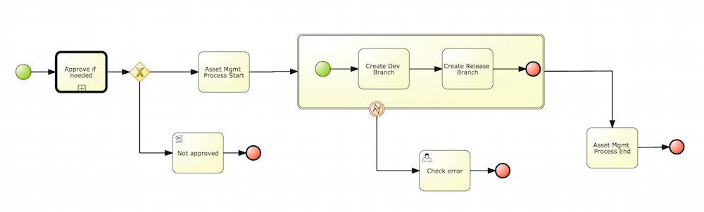
By default the asset management feature is not enabled so make sure to select Managed Repository on the New Repository Wizzard. When we work inside a managed repository, the development branch is selected for the users to work on. If multiple dev branches are created, the user will need to pick one.
3.10.3.2. Promote Changes Process
When some work is done in the developments branch and the users reach a point where the changes needs to be tested before going into production, they will start a new Promote Changes process so a more technical user can decide and review what needs to be promoted. The users belonging to the "kiemgmt" group will see a new Task in their Group Task List which will contain all the files that had being changed. The user needs to select the assets that will be promoting via the UI. The underlying process will be cherry-picking the commits selected by the user to the release branch. The user can specify that a review is needed by a more technical user.
This process can be repeated multiple times if needed before creating the artifacts for the release.
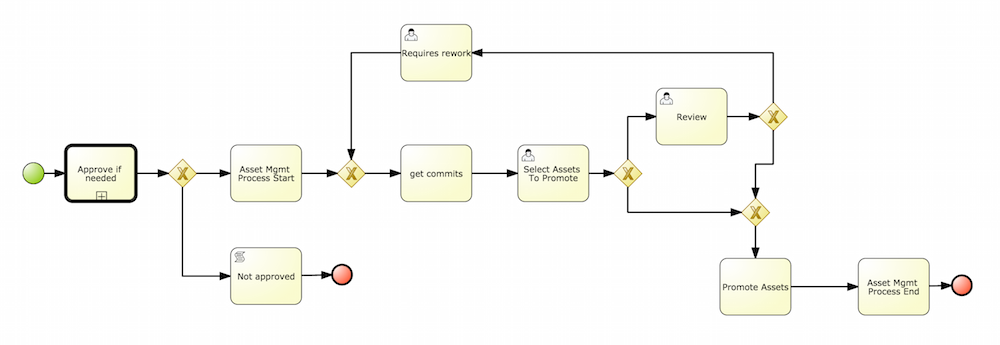
3.10.3.3. Build Process
The Build process can be triggered to build our projects from different branches. This allows us to have a more flexible way to build and deploy our projects to different runtimes.
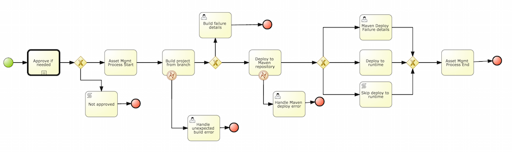
3.10.3.4. Release Process
The release process is triggered at any time when the user decided that it is time to generate a release of the project that he/she is working on. This process will build the project (calling the Build Process) and it will update all the maven artifacts to the next version.
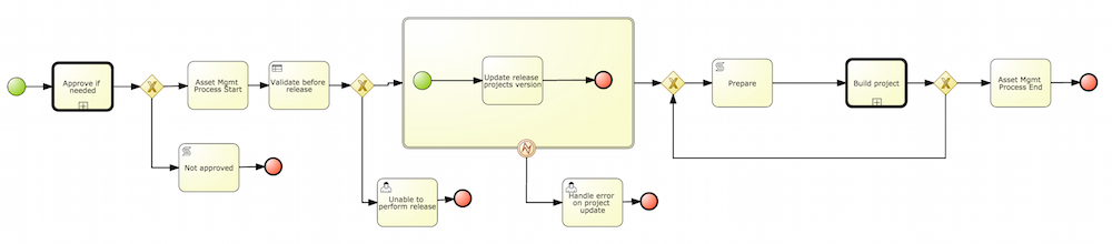
3.10.4. Usage Flow
This section describes the common usage flow for the asset management features showing all the screens involved.
The first contact with the Asset Management features starts on the Repository creation.
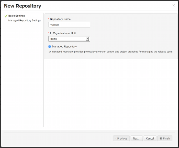
If the user chooses to create a Managed Respository a new page in the wizzard is enabled:
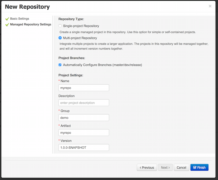
When a managed repository is created the assets management configuration process is automatically launched in order to create the repository branches, and the corresponding project structure is also created.
3.11. Execution Server Management UI
The Execution Server Management UI allows users create and modify Server Templates and Containers, it also allows users manage Remote Servers. This screen is available via Deploy → Rule Deployments menu.
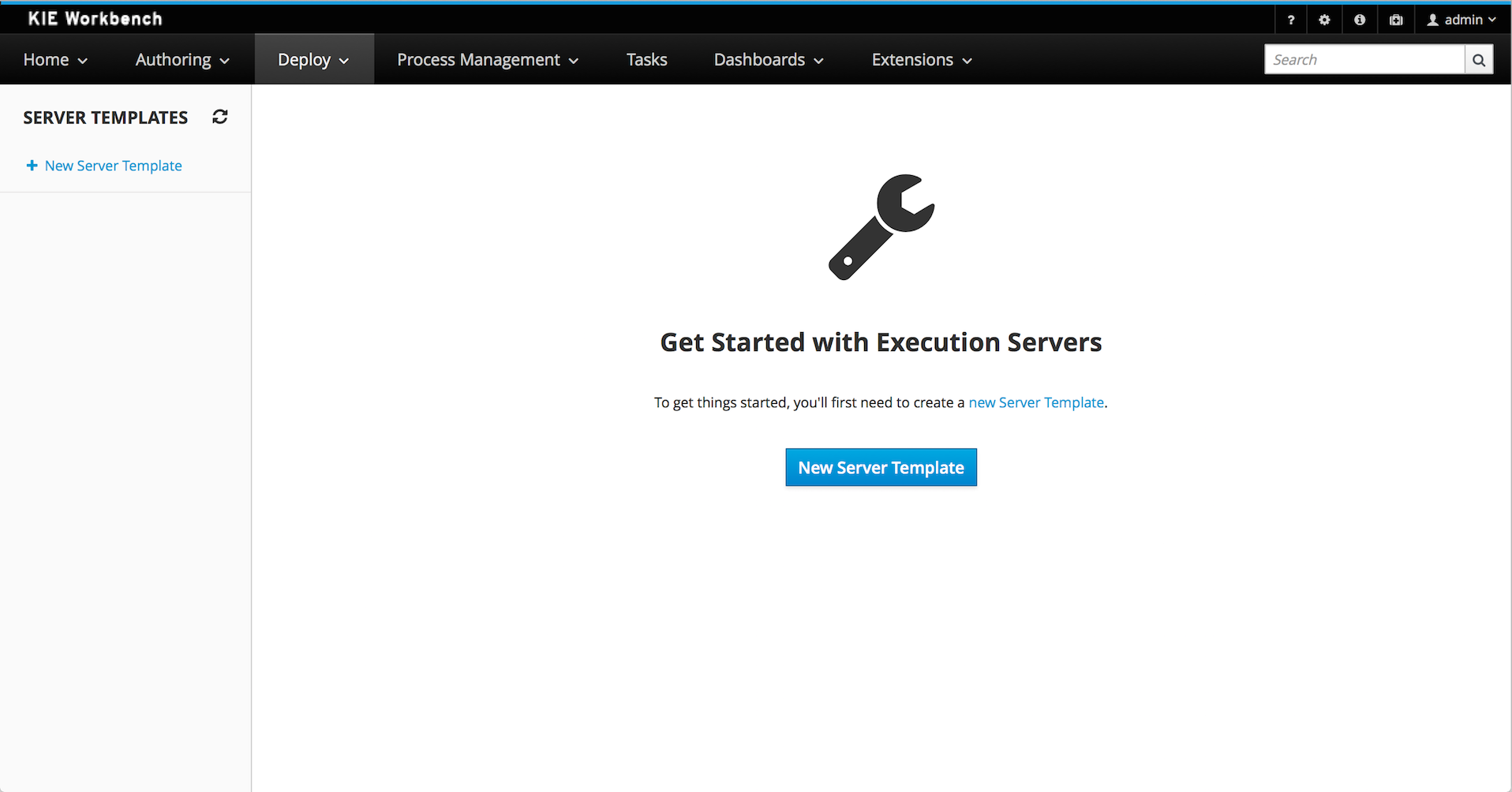
|
The management UI is only available for KIE Managed Servers. |
3.11.1. Server Templates
Server templates are used to define a common configuration that can be used for multiple server, thus the name: Template.
Server Templates can be created directly from the management UI or it’s automatically create when a server connects to controller and there isn’t a template definition for that remote server. Server templates may have one or more capabilities, such capabilities can’t be modified, if you need modify the capabilities you’ll have to create a new template. Here is the list of current capabilities:
-
Rule (Drools)
-
Process (jBPM)
-
Planning (Optaplanner)
|
For Planner capability it’s mandatory to enable Rule’s capability too. |
In order to create a new Server Template you have to click at New Server Template button and follow the wizard. It’s also possible to create a container during Wizard, but for now let’s limit to just the template.
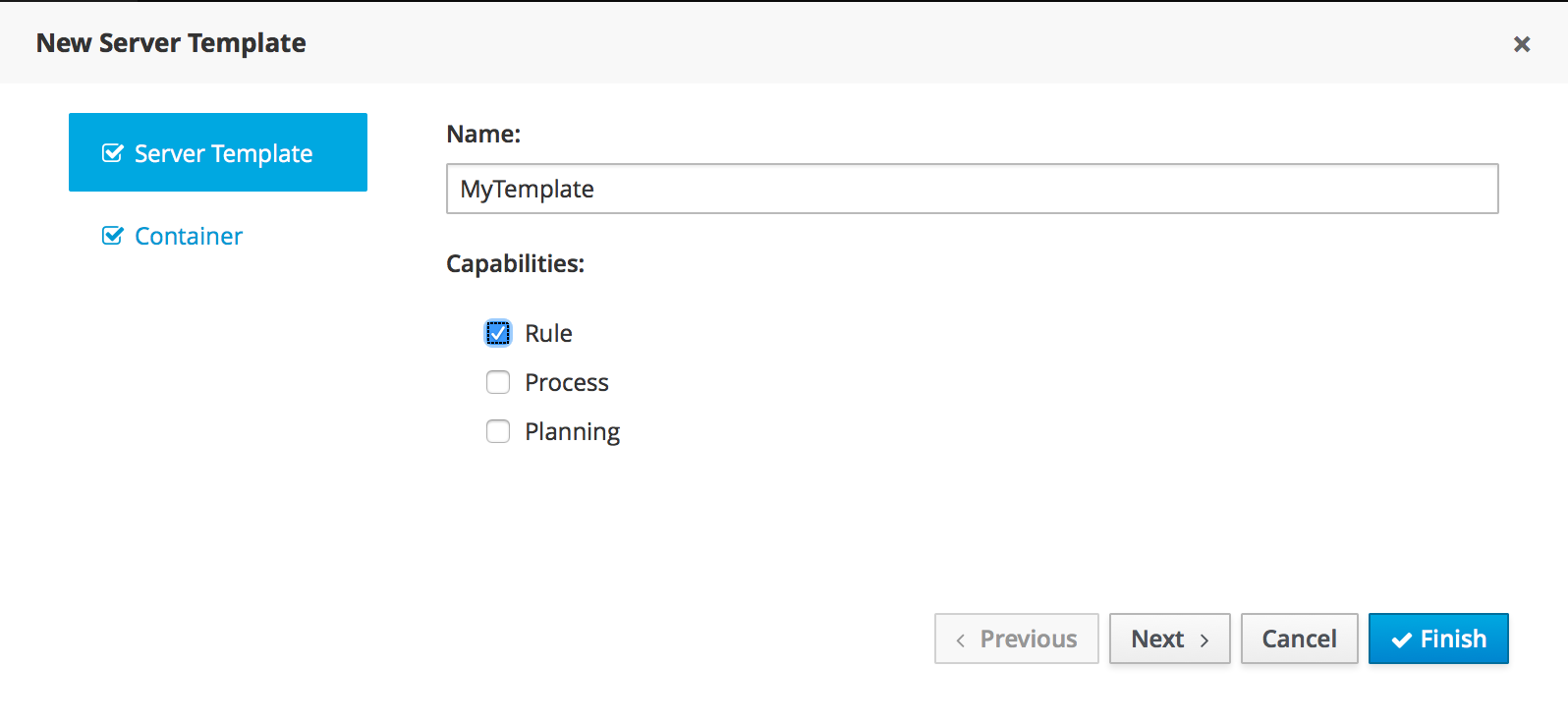
Once created you’ll get the new Template listed on the left hand side, with the new Server Template highlighted. On the right hand side you get the 2nd level navigation that lists Containers and Remote Servers that are related to selected Server Template.
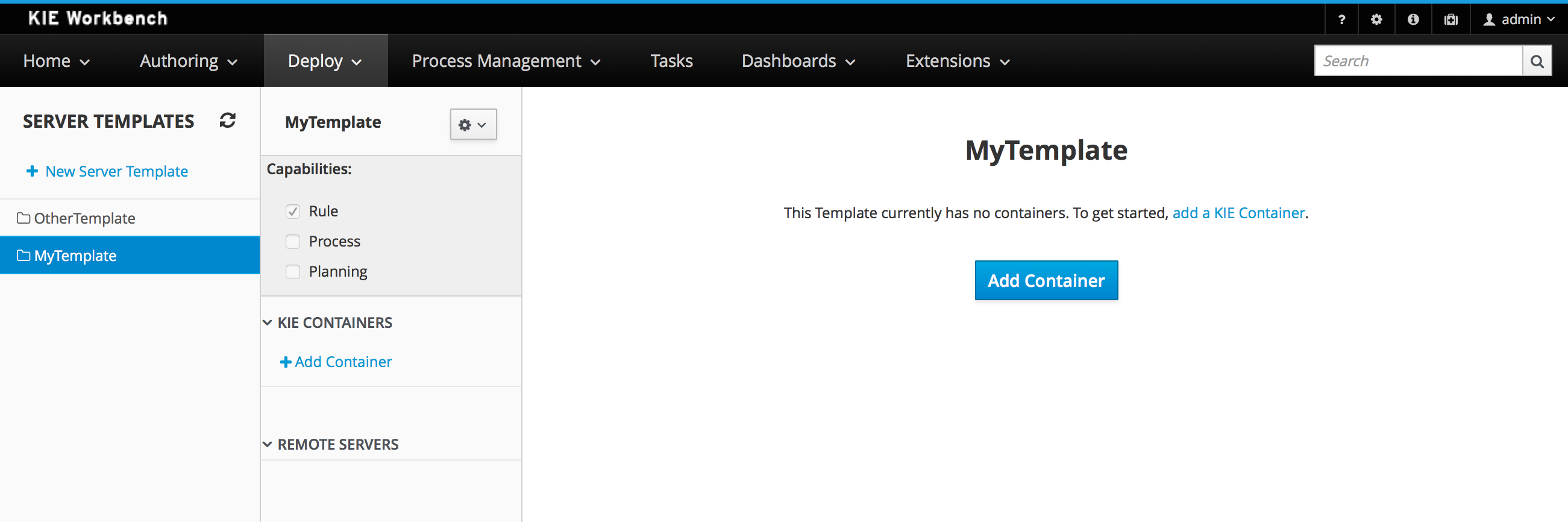
On top of the navigation is also possible to delete the current Server Template or create a copy of it.
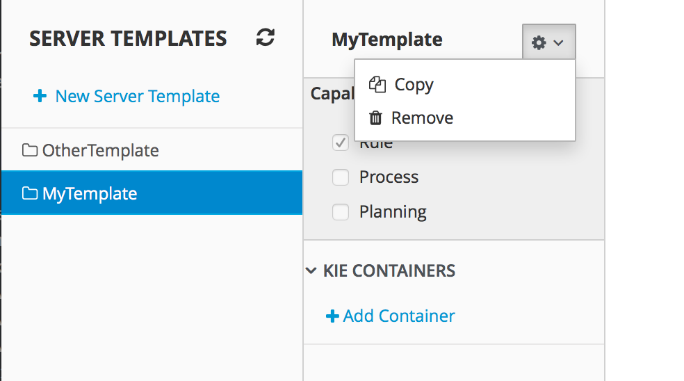
3.11.2. Container
A Container is a KIE Container configuration of the Server Template. Click the Add Container button to create a new container for the current Server Template.
The search area can help users find an specific KJARs that they are looking for.
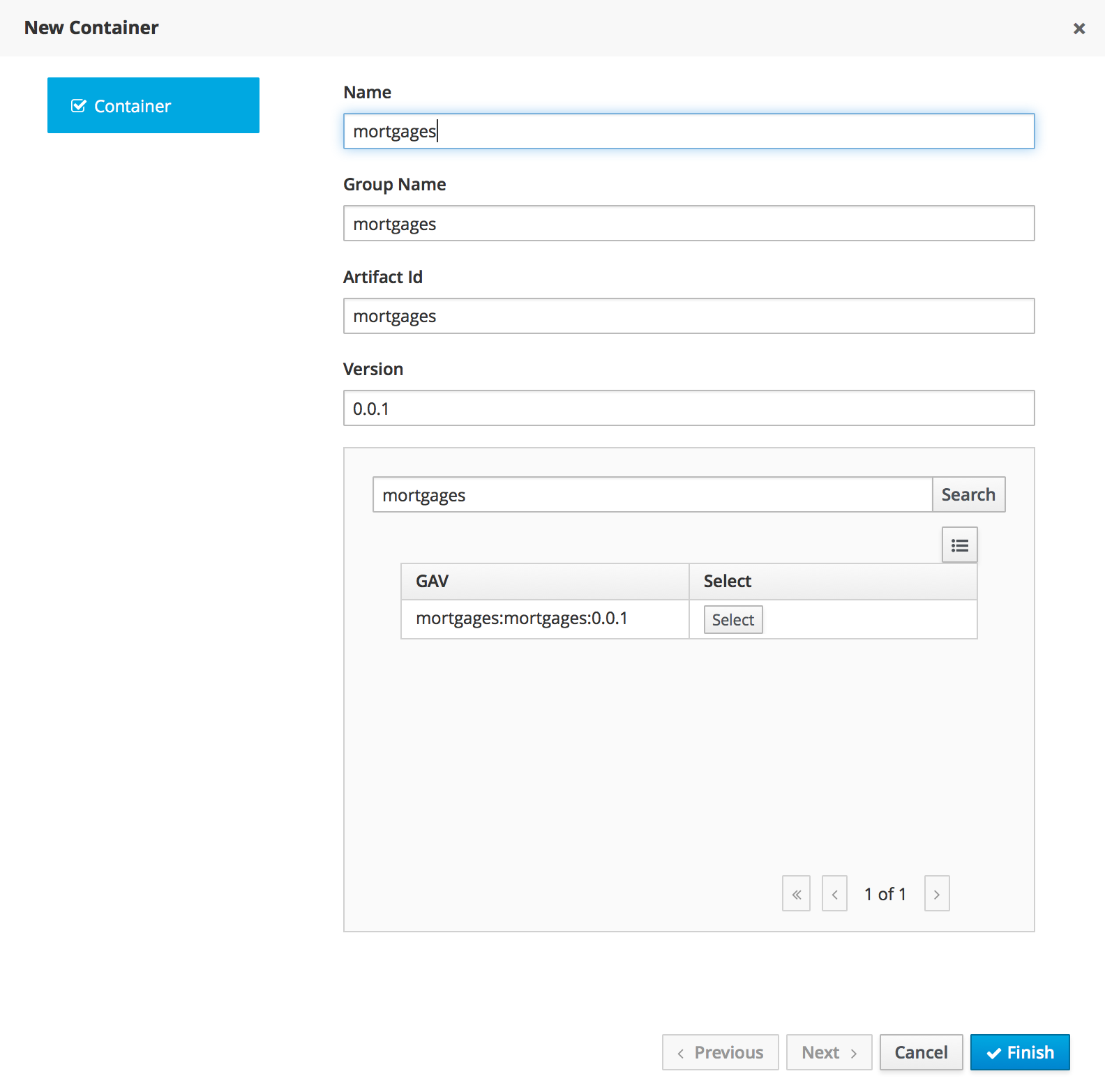
For Server Templates that have Process capabilities enabled, the Wizard has a 2nd optional step where users can configure some process related behaviors.
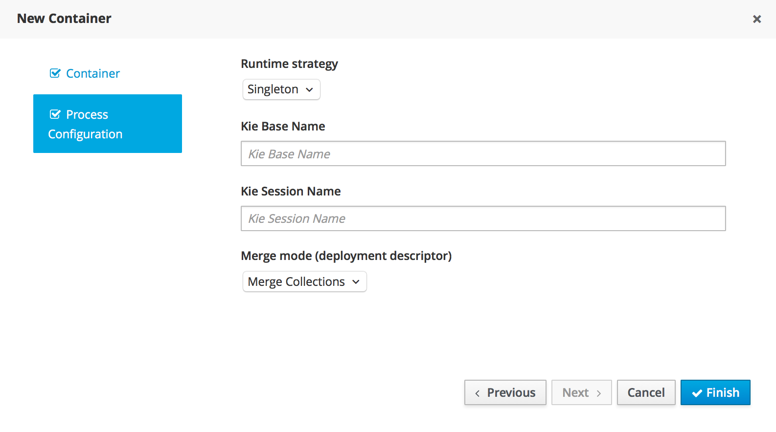
Kie Base Name determines which Kie Base of the deployed artifact will be used.
Kie Session Name determines which Kie Session of the selected Kie Base will be used.
|
Please notice that configurations on this tab takes effect only if the deployed project contains some business processeses. It is not enough if the server template has the extension for processes enabled. |
Once created the new Container will be displayed on the containers list just above the list of remote servers. Just after created a container is by default Stopped which is the only state that allows users to remove it.
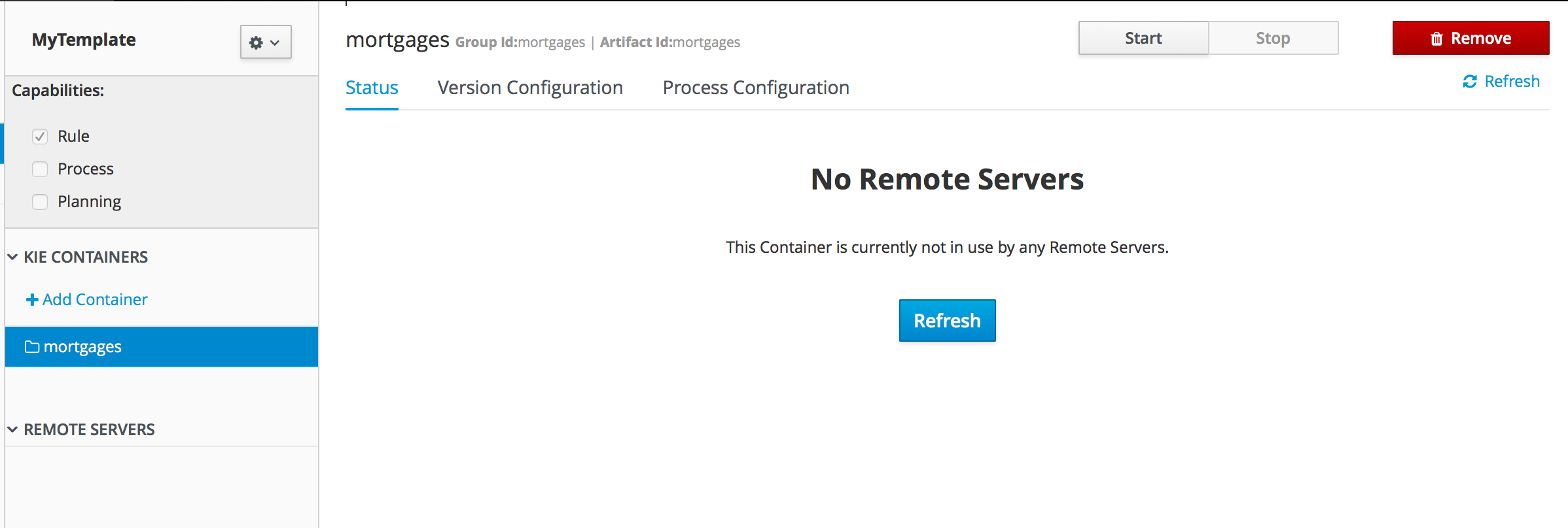
A Container has the following tabs available for management and/or configuration:
-
Status
-
Version Configuration
-
Process Configuration
Status tab lists all the Remote Servers that are running the active Container. Each Remote Server is rendered as a Card, which displays to users status and endpoint.
|
Only started Containers are deployed to remote servers. |
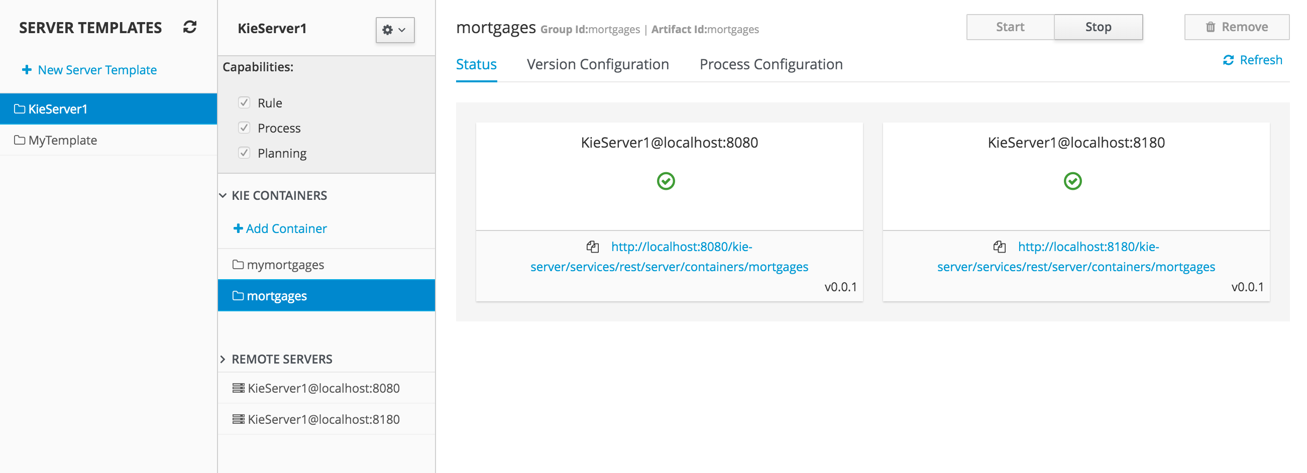
For containers that do not have process capability the Version Configuration tab allows users to change the current version of the Container. Users can upgrade manually to a specific version using the "Upgrade" button or enable/disable the Scanner. It’s also possible to execute a Scan Now operation that will scan for new versions only once.
To redeploy SNAPSHOT kjars with your latest changes all existing containers with that version must first be removed. Executing 'build and deploy' will then create a container with the latest SNAPSHOT kjar. However, this is not possible for release versions. Following maven release convensions if the GAV of a kjar is anthing but SNAPSHOT, the GAV will need to be updated to the newer release version and deployed to its own container. The new release version can also be used to upgrade an existing container as describe previously provided the container does not have process capability.
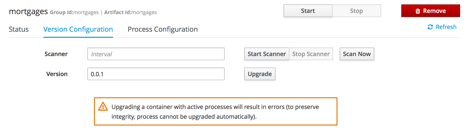
Process Configuration is the same form that is displayed during New Container Wizard for Template Servers that have Process Capability. If Template Server doesn’t have such capability, the action buttons will be disabled.
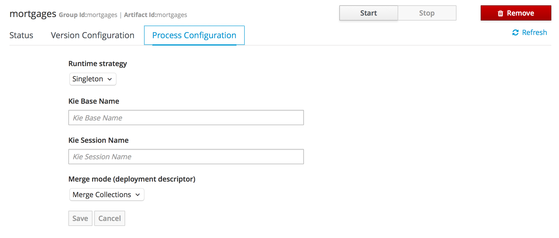
3.11.3. Remote Server
Remote Server is a Managed KIE Server instance running that has a controller configured.
|
By default Workbench comes with a Controller embedded. |
The list of Remote Servers are displayed just under the list of Containers. Once selected the screens reveals the Remote Server details and a list of cards, each card represents a running Container.
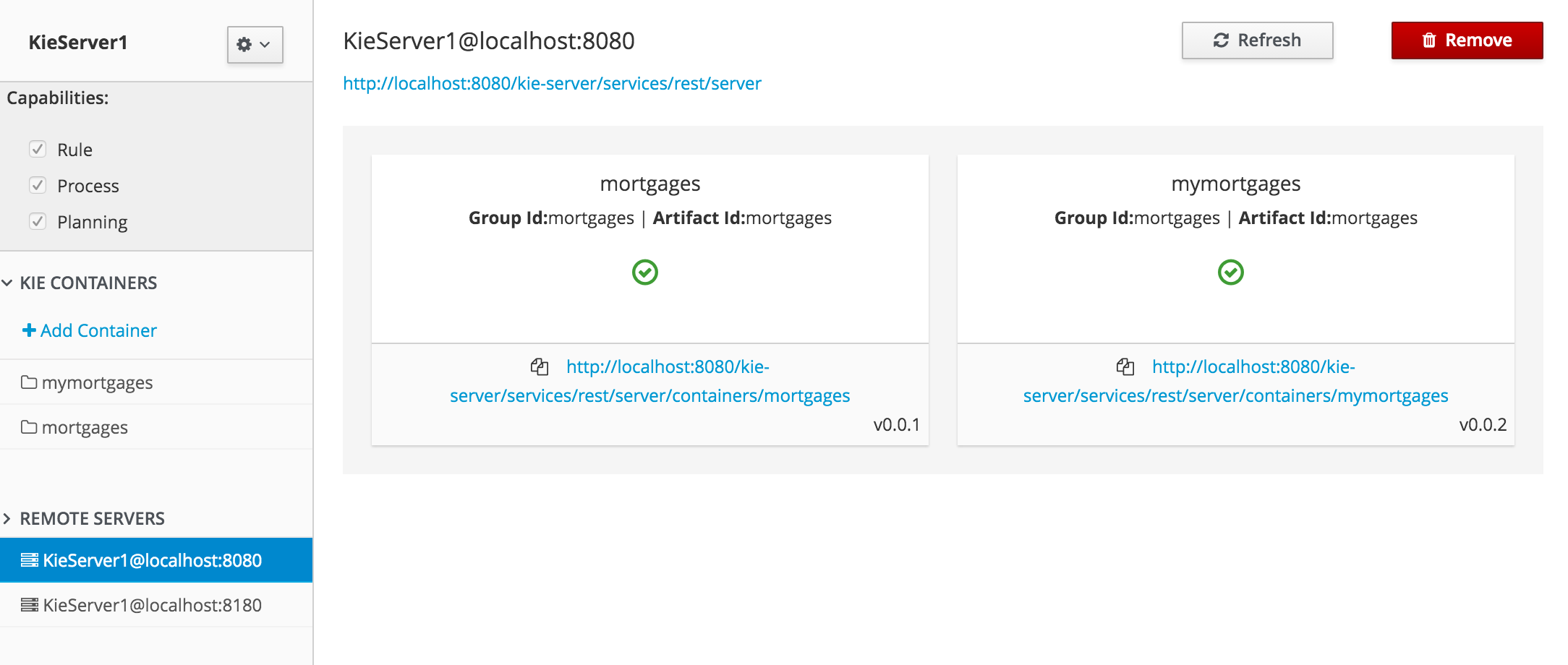
4. Authoring Planning Assets
4.1. Solver Editor
The solver editor creates a solver configuration that can be run in the Execution Solver or plain Java code after the kjar is deployed.
|
To see and use this editor, the user needs to have the |
Use the Validate button to validate the solver configuration. This will actually build a Solver, so most issues in your project will present itself then, without the need to deploy and run it.
By default, the solver configuration automatically scans for all planning entities and planning solution classes. If none are found (or too many), validation fails.
4.1.1. Score Director Factory
Use the Score Director Factory configuration section to define a knowledge base, which contains scoring rule definitions. Select one of the knowledge sessions defined within the knowledge base. The sessions can be managed in the Project Editor.
|
Planner uses a default knowledge session if none is specified. |
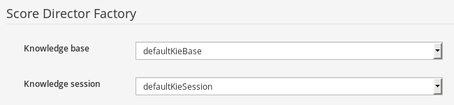
4.1.2. Termination Editor
By default, a time period that the planning engine is given to solve a problem instance is not limited. While this might be enforced by some scenarios (e.g. real-time planning), it is useful to have a mechanism to control total duration of the solving process.
Refer to OptaPlanner documentation for more information on supported termination types.
|
Solver can be terminated manually using REST API of the KIE Server. |
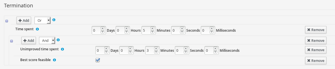
Use Add to create new termination element within selected logical group and pick termination type. Input field will be displayed based on the selection.
Termination elements are organized into a tree structure. The editor supports definition of logical groups (represented by termination type Nested termination), which join multiple termination elements using logical operators (And/Or). The scope of the operator is limited by the logical group in which it is defined.
Click Remove to remove the termination element from the termination tree. If the removal action is performed on the root element of a logical group, all its children will be removed as well.
4.1.3. Phase Configuration
Planner splits the solving process into multiple phases. Every phase represents a single optimization algorithm run, which consumes a result returned by the previous phase. For example, a Construction Heuristic phase is usually placed before a Local Search phase to provide a good initial solution that the Local Search further optimizes.
|
By default, the Solver uses a single Construction Heuristic phase followed by a Local Search phase. |
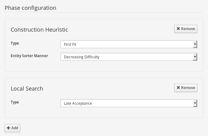
Click Add to add a new phase. Individual phase elements provide additional configuration options. Click Remove to remove a specific phase from the Solver configuration.
4.2. Domain Editor
Planner leverages Data modeller to create domain model for constraint satisfaction problems.
In addition to the basic functionality the Data modeller provides (creating data objects and their properties), the Workbench allows enhancing the data model with Planner-specific data object roles (Planning Solution, Planning Entity) in a user-friendly way. The options are available in the Planner dock.
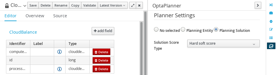
The content of the dock varies depending on the current selection. Selecting a data object results in displaying top-level settings defined on data object level (Planning Solution, Planning Entity). On the other hand, selecting properties of the data object results in displaying fine-grained settings defined on property level of the data object.
The overview of the Planner dock capabilities is shown in the following division:
Data object level
Property level
4.2.1. Planning Entity Difficulty Comparator
Specified on Planning entity level, the Difficulty comparator provides a way to determine which Planning entities are more difficult to plan. This helps optimization algorhitms to work in an efficient manner. Refer to OptaPlanner documentation for more details.
The Difficulty comparator definition tool is present in the Planner dock of the Data modeler and becomes available once a PlanningEntity selection is performed on a data object.
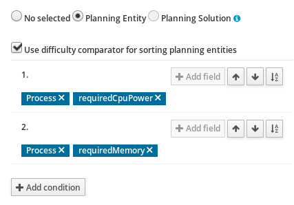
Click Add condition to add new sorting criteria for given planning entity. Once the criterion is added, Clicking Add field allows the user to select fields which will be used for difficulty comparison.
There are 2 types of fields:
-
Basic - value types (e.g. number, String)
-
Data object - complex types having nested attributes
Data object types allow nesting deep into object hierarchy, until a basic type is encountered. In this situation Add field button is no longer displayed. Sorting criteria are ordered. The ones defined first are prioritized when Planner engine resolves planning entity difficulty.
Click on the Remove icon within a label to remove the field from the sorting criteria. If the field is of type Data object, all its children are removed as well.
Click Arrow up, Arrow down to change the priority of the criterion by moving it up/down.
Select Sort order icon to define whether given criterion should be applied to sort the planning entities in ascending or descending order.
4.3. Guided Rule Editor
To solve an optimization problem, define score constraints that evaluate your solution. Planner integrates with the Guided Rule Editor and provides score modifiers which are used by the engine during the solving process.
Score modifiers can be accessed in the action selector (+) of the THEN (right-hand side) section of a rule, provided the Planning Solution is defined within the project.
|
Make sure to define a Planning Solution before proceeding to a rule creation. |
There are two types of Planner actions in the Guided Rule Editor:
-
Modify a single score level - use the action to modify only one score component (e.g. hard score)
-
Modify multiple score levels - use the action to modify multiple score components at the same time (e.g. hard and soft score)
Once the action is selected, Planner score input appears on the THEN (right-hand side) section of the rule. Insert the value of a constraint into the text input. Click Validate to verify the correctness of the inserted value.

5. Workbench Integration
5.1. REST
REST API calls to Knowledge Store allow you to manage the Knowledge Store content and manipulate the static data in the repositories of the Knowledge Store. The calls are asynchronous, that is, they continue their execution as a job after a call was performed. The job ID is returned by every call to allow (after the REST API call was performed) to request the job status and verify whether the job finished successfully. Parameters of these calls are provided in the form of JSON entities.
When using Java code to interface with the REST API, the classes used in POST operations or otherwise returned by various operations can be found in the (org.kie.workbench.services:)kie-wb-common-services JAR.
All of the classes mentioned below can be found in the org.kie.workbench.common.services.shared.rest package in that JAR.
5.1.1. Job calls
Every Knowledge Store REST call returns its job ID after it was sent. This is necessary as the calls are asynchronous and you need to be able to reference the job to check its status as it goes through its lifecycle. During its lifecycle, a job can have the following statuses:
-
ACCEPTED: the job was accepted and is being processed -
BAD_REQUEST: the request was not accepted as it contained incorrect content -
RESOURCE_NOT_EXIST: the requested resource (path) does not exist -
DUPLICATE_RESOURCE: the resource already exists -
SERVER_ERROR: an error on the server occurred -
SUCCESS: the job finished successfully -
FAIL: the job failed -
DENIED: the job was denied -
GONE: the job ID could not be foundA job can be GONE in the following cases: The job was explicitly removed The job finished and has been deleted from the status cache (the job is removed from status cache after the cache has reached its maximum capacity) ** The job never existed
The following job calls are provided:
- [GET]
/jobs/{jobID} -
Returns the job status
- [DELETE]
/jobs/{jobID} -
Removes the job: If the job is not yet being processed, this will remove the job from the job queue. However, this will not cancel or stop an ongoing job
5.1.2. Repository calls
Repository calls to the Knowledge Store allow you to manage Git repositories and projects inside them.
The following repositories calls are provided:
- [GET]
/repositories -
Gets information about the repositories in the Knowledge Store
- [GET]
/repositories/{repositoryName} -
Gets information about the repository
- [POST]
/repositories -
Creates a new empty repository or a new repository cloned from an existing (git) repository defined by
RepositoryRequestJSON entity - [DELETE]
/repositories/{repositoryName} -
Removes the repository from the Knowledge Store
- [GET]
/repositories/{repositoryName}/projects/ -
Gets information about all projects in the repository
- [POST]
/repositories/{repositoryName}/projects/ -
Creates a project in the repository defined by
ProjectRequestJSON entity - [DELETE]
/repositories/{repositoryName}/projects/{projectName} -
Deletes the project in the repository
5.1.3. Organizational unit calls
Organizational unit calls to the Knowledge Store allow you to manage organizational units and organize the connected Git repositories.
The following organizationalUnits calls are provided:
- [GET]
/organizationalunits -
Gets all organizational units
- [GET]
/organizationalunits/{organizationalUnitName} -
Gets a single organizational unit
- [POST]
/organizationalunits -
Creates an organizational unit described by
OrganizationalUnitJSON entity - [POST]
/organizationalunits/{organizationalUnitName} -
Updates the organizational unit described by
OrganizationalUnitJSON entity - [DELETE]
/organizationalunits/{organizationalUnitName} -
Deletes the organizational unit
- [POST]
/organizationalunits/{organizationalUnitName}/repositories/{repositoryName} -
Adds the repository to the organizational unit
- [DELETE]
/organizationalunits/{organizationalUnitName}/repositories/{repositoryName} -
Removes the repository from the organizational unit
5.1.4. Maven calls
Maven calls to a project in the Knowledge Store allow you compile, test, install, and deploy projects.
The following maven calls are provided:
- [POST]
/repositories/{repositoryName}/projects/{projectName}/maven/compile -
Compiles the project (equivalent to
mvn compile) - [POST]
/repositories/{repositoryName}/projects/{projectName}/maven/test -
Tests the project (equivalent to
mvn test) - [POST]
/repositories/{repositoryName}/projects/{projectName}/maven/install -
Installs the project (equivalent to
mvn install) - [POST]
/repositories/{repositoryName}/projects/{projectName}/maven/deploy -
Deploys the project (equivalent to
mvn deploy)
5.1.5. REST summary
The URL templates in the table below are relative the following URL:
-
http://{server}:{port}/kie-wb/rest
| URL Template | Type | Description |
|---|---|---|
/jobs/{jobID} |
GET |
return the job status |
/jobs/{jobID} |
DELETE |
remove the job |
/organizationalunits |
GET |
return a list of organizational units |
/organizationalunits/{organizationalUnitName} |
GET |
return a single organizational unit |
/organizationalunits |
POST |
create an organizational unit |
/organizationalunits/{organizationalUnitName} |
POST |
update the organizational unit |
/organizationalunits/{organizationalUnitName} |
DELETE |
delete the organizational unit |
/organizationalunits/{organizationalUnitName}/repositories/{repositoryName} |
POST |
add the repository to the organizational unit |
/organizationalunits/{organizationalUnitName}/repositories/{repositoryName} |
DELETE |
remove the repository from the organizational unit |
/repositories |
GET |
return a list of repositories |
/repositories/{repositoryName} |
GET |
return a single repository |
/repositories |
POST |
create or clone the repository |
/repositories/{repositoryName} |
DELETE |
remove the repository |
/repositories/{repositoryName}/projects |
GET |
get a list of projects in the repository |
/repositories/{repositoryName}/projects |
POST |
create a project in the repository |
/repositories/{repositoryName}/projects/{projectName} |
DELETE |
delete the project in the repository |
/repositories/{repositoryName}/projects/{projectName}/maven/compile |
POST |
compile the project |
/repositories/{repositoryName}/projects/{projectName}/maven/test |
POST |
test the project |
/repositories/{repositoryName}/projects/{projectName}/maven/install |
POST |
install the project |
/repositories/{repositoryName}/projects/{projectName}/maven/deploy |
POST |
deploy the project |
5.2. Keycloak SSO integration
Single Sign On (SSO) and related token exchange mechanisms are becoming the most common scenario for the authentication and authorization in different environments on the web, specially when moving into the cloud.
This section talks about the integration of Keycloak with jBPM or Drools applications in order to use all the features provided on Keycloak. Keycloak is an integrated SSO and IDM for browser applications and RESTful web services. Lean more about it in the Keycloak’s home page.
The result of the integration with Keycloak has lots of advantages such as:
-
Provide an integrated SSO and IDM environment for different clients, including jBPM and Drools workbenches
-
Social logins - use your Facebook, Google, Linkedin, etc accounts
-
User session management
-
And much more…
Next sections cover the following integration points with Keycloak:
-
Workbench authentication through a Keycloak server
It basically consists of securing both web client and remote service clients through the Keycloak SSO. So either web interface or remote service consumers ( whether a user or a service ) will authenticate into trough KC.
-
Execution server authentication through a Keycloak server
Consists of securing the remote services provided by the execution server (as it does not provides web interface). Any remote service consumer ( whether a user or a service ) will authenticate trough KC.
-
Consuming remote services
This section describes how a third party clients can consume the remote service endpoints provided by both Workbench and Execution Server, such as the REST API or remote file system services.
5.2.1. Scenario
Consider the following diagram as the environment for this document’s example:
Keycloak is a standalone process that provides remote authentication, authorization and administration services that can be potentially consumed by one or more jBPM applications over the network.
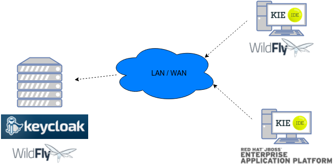
Consider these main steps for building this environment:
-
Install and setup a Keycloak server
-
Create and setup a Realm for this example - Configure realm’s clients, users and roles
-
Install and setup the SSO client adapter & jBPM application
Note: The resulting environment and the different configurations for this document are based on the jBPM (KIE) Workbench, but same ones can also be applied for the KIE Drools Workbench as well.
5.2.2. Install and setup a Keycloak server
Keycloak provides an extensive documentation and several articles about the installation on different environments. This section describes the minimal setup for being able to build the integrated environment for the example. Please refer to the Keycloak documentation if you need more information.
Here are the steps for a minimal Keycloak installation and setup:
-
Download latest version of Keycloak from the Downloads section. This example is based on Keycloak 1.9.0.Final
-
Unzip the downloaded distribution of Keycloak into a folder, let’s refer it as
$KC_HOME -
Run the KC server - This example is based on running both Keycloak and jBPM on same host. In order to avoid port conflicts you can use a port offset for the Keycloak’s server as:
$KC_HOME/bin/standalone.sh -Djboss.socket.binding.port-offset=100 -
Create a Keycloak’s administration user - Execute the following command to create an admin user for this example:
$KC_HOME/bin/add-user.sh -r master -u 'admin' -p 'admin'
The Keycloak administration console will be available at http://localhost:8180/auth/admin (use the admin/admin for login credentials).
5.2.3. Create and setup the demo realm
Security realms are used to restrict the access for the different application’s resources.
Once the Keycloak server is running next step is about creating a realm. This realm will provide the different users, roles, sessions, etc for the jBPM application/s.
Keycloak provides several examples for the realm creation and management, from the official examples to different articles with more examples.
Follow these steps in order to create the demo realm used later in this document:
-
Go to the Keycloak administration console and click on Add realm button. Give it the name demo.
-
Go to the Clients section (from the main admin console menu) and create a new client for the demo realm:
-
Client ID: kie
-
Client protocol: openid-connect
-
Acces type: confidential
-
Root URL: http://localhost:8080
-
Base URL: /kie-wb-6.4.0.Final
-
Redirect URIs: /kie-wb-6.4.0.Final/*
-
The resulting kie client settings screen:
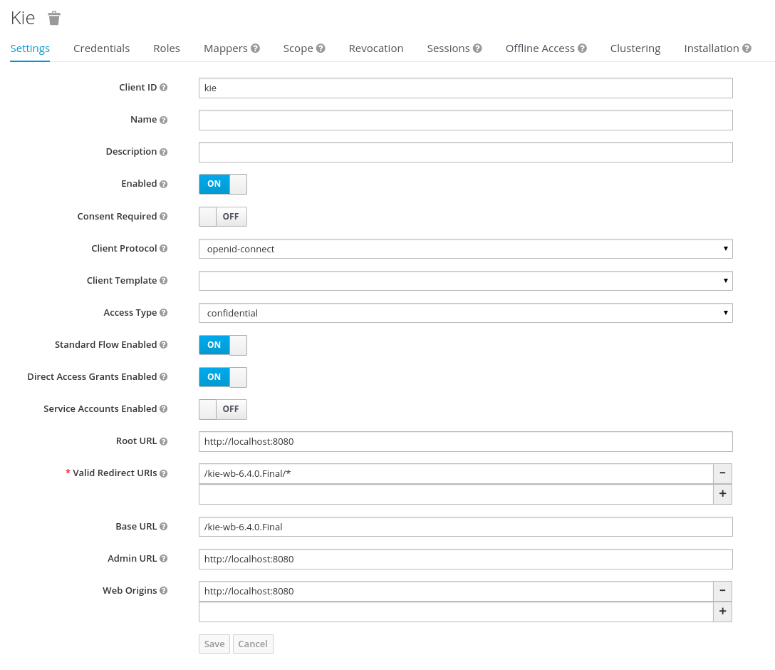
Note: As you can see in the above settings it’s being considered the value kie-wb-6.4.0.Final for the application’s context path. If your jbpm application will be deployed on a different context path, host or port, just use your concrete settings here.
Last step for being able to use the demo realm from the jBPM workbench is create the application’s user and roles:
-
Go to the Roles section and create the roles admin,_kiemgmt and _rest-all
-
Go to the Users section and create the admin user. Set the password with value "password" in the credentials tab, unset the temporary switch.
-
In the Users section navigate to the Role Mappings tab and assign the admin, kiemgmt and rest-all roles to the admin user
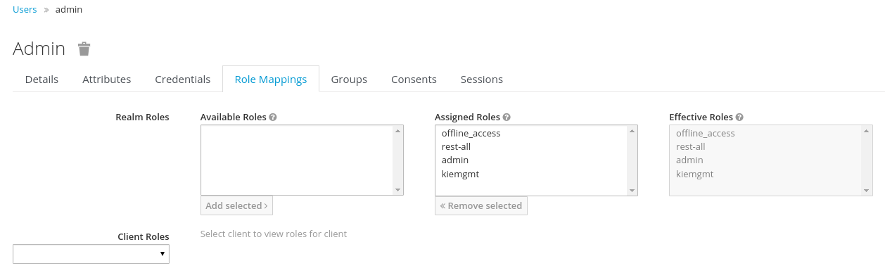
At this point a Keycloak server is running on the host, setup with a minimal configuration set. Let’s move to the jBPM workbench setup.
5.2.4. Install and setup jBPM Workbench
For this tutorial let’s use a Wildfly as the application server for the jBPM workbench, as the jBPM installer does by default.
Let’s assume, after running the jBPM installer, the $JBPM_HOME as the root path for the Wildfly server where the application has been deployed.
5.2.4.1. Install the KC adapter
In order to use the Keycloak’s authentication and authorization modules from the jBPM application, the Keycloak adapter for Wildfly must be installed on our server at $JBPM_HOME. Keycloak provides multiple adapters for different containers out of the box, if you are using another container or need to use another adapter, please take a look at the adapters configuration from Keycloak docs. Here are the steps to install and setup the adapter for Wildfly 8.2.x:
-
Download the adapter from here
-
Execute the following commands on your shell:
cd $JBPM_HOME/unzip keycloak-wf8-adapter-dist.zip // Install the KC client adapter

cd $JBPM_HOME/bin
./standalone.sh -c standalone-full.xml // Setup the KC client adapter.

// ** Once server is up, open a new command line terminal and run:
cd $JBPM_HOME/bin
./jboss-cli.sh -c --file=adapter-install.cli
5.2.4.2. Configure the KC adapter
Once installed the KC adapter into Wildfly, next step is to configure the adapter in order to specify different settings such as the location for the authentication server, the realm to use and so on.
Keycloak provides two ways of configuring the adapter:
-
Per WAR configuration
-
Via Keycloak subsystem
In this example let’s use the second option, use the Keycloak subsystem, so our WAR is free from this kind of settings. If you want to use the per WAR approach, please take a look here.
Edit the configuration file $JBPM_HOME/standalone/configuration/standalone-full.xml and locate the subsystem configuration section. Add the following content:
<subsystem xmlns="urn:jboss:domain:keycloak:1.1">
  <secure-deployment name="kie-wb-6.4.0-Final.war">
    <realm>demo</realm>
    <realm-public-key>MIIBIjANBgkqhkiG9w0BAQEFAAOCA...</realm-public-key>
    <auth-server-url>http://localhost:8180/auth</auth-server-url>
    <ssl-required>external</ssl-required>
    <resource>kie</resource>
    <enable-basic-auth>true</enable-basic-auth>
    <credential name="secret">925f9190-a7c1-4cfd-8a3c-004f9c73dae6</credential>
    <principal-attribute>preferred_username</principal-attribute>
  </secure-deployment>
</subsystem>
If you have imported the example json files from this document in step 2, you can just use same configuration as above by using your concrete deployment name . Otherwise please use your values for these configurations:
-
Name for the secure deployment - Use your concrete application’s WAR file name
-
Realm - Is the realm that the applications will use, in our example, the demo realm created the previous step.
-
Realm Public Key - Provide here the public key for the demo realm. It’s not mandatory, if it’s not specified, it will be retrieved from the server. Otherwise, you can find it in the Keycloak admin console → Realm settings ( for demo realm ) → Keys
-
Authentication server URL - The URL for the Keycloak’s authentication server
-
Resource - The name for the client created on step 2. In our example, use the value kie.
-
Enable basic auth - For this example let’s enable Basic authentication mechanism as well, so clients can use both Token (Baerer) and Basic approaches to perform the requests.
-
Credential - Use the password value for the kie client. You can find it in the Keycloak admin console → Clients → kie → Credentials tab → Copy the value for the secret.
For this example you have to take care about using your concrete values for secure-deployment name, realm-public-key and credential password. You can find detailed information about the KC adapter configurations here.
5.2.4.3. Run the environment
At this point a Keycloak server is up and running on the host, and the KC adapter is installed and configured for the jBPM application server. You can run the application using:
$JBPM_HOME/bin/standalone.sh -c standalone-full.xmlYou can navigate into the application once the server is up at:
http://localhost:8080/kie-wb-6.4.0.Final
Use your Keycloak’s admin user credentials to login: admin/password.
5.2.5. Securing workbench remote services via Keycloak
Both jBPM and Drools workbenches provides different remote service endpoints that can be consumed by third party clients using the remote API.
In order to authenticate those services thorough Keycloak the BasicAuthSecurityFilter must be disabled, apply those modifications for the the WEB-INF/web.xml file (app deployment descriptor) from jBPM’s WAR file:
-
Remove the following filter from the deployment descriptor:
<filter> <filter-name>HTTP Basic Auth Filter</filter-name> <filter-class>org.uberfire.ext.security.server.BasicAuthSecurityFilter</filter-class> <init-param> <param-name>realmName</param-name> <param-value>KIE Workbench Realm</param-value> </init-param> </filter> <filter-mapping> <filter-name>HTTP Basic Auth Filter</filter-name> <url-pattern>/rest/*</url-pattern> <url-pattern>/maven2/*</url-pattern> <url-pattern>/ws/*</url-pattern> </filter-mapping> -
Constraint the remote services URL patterns as:
<security-constraint>
  <web-resource-collection>
    <web-resource-name>remote-services</web-resource-name>
    <url-pattern>/rest/*</url-pattern>
    <url-pattern>/maven2/*</url-pattern>
    <url-pattern>/ws/*</url-pattern>
  </web-resource-collection>
  <auth-constraint>
    <role-name>rest-all</role-name>
  </auth-constraint>
</security-constraint>
Important note: The user that consumes the remote services must be member of role rest-all. As on described previous steps, the admin user in this example it’s already a member of the rest-all role.
5.2.6. Securing workbench’s file system services via Keycloak
In order to consume other remote services such as the file system ones (e.g. remote GIT), a specific Keycloak login module must be used for the application’s security domain in the $JBPM_HOME/standalone/configuration/standalone-full.xml file. By default the workbench uses the other security domain, so the resulting configuration on the _$JBPM_HOME/standalone/configuration/standalone-full.xml should be such as:
<security-domain name="other" cache-type="default">
    <authentication>
        <login-module code="org.keycloak.adapters.jaas.DirectAccessGrantsLoginModule" flag="required">
            <!-- Parameter value can be a file system absolute path or a classpath (e.g. "classpath:/some-path/kie-git.json")-->
            <module-option name="keycloak-config-file" value="$JBPM_HOME/kie-git.json"/>
        </login-module>
    </authentication>
</security-domain>
Note that:
-
The login modules on the other security domain in the $JBPM_HOME/standalone/configuration/standalone-full.xml file must be REPLACED by the above given one.
-
Replace $JBPM_HOME/kie-git.json by the path (on file system) or the classpath (e.g. classpath:/some-path/kie-git.json) for the json configuration file used for the remote services client. Please continue reading in order to create this Keycloak client and how to obtain this json file.
At this point, remote services that use JAAS for the authentication process, such as the file system ones ( e.g. GIT ), are secured by Keycloak using the client specified in the above json configuration file. So let’s create this client on Keycloak and generate the required JSON file:
-
Navigate to the KC administration console and create a new client for the demo realm using kie-git as name.
-
Enable Direct Access Grants Enabled option
-
Disable Standard Flow Enabled option
-
Use a confidential access type for this client. See below image as example:
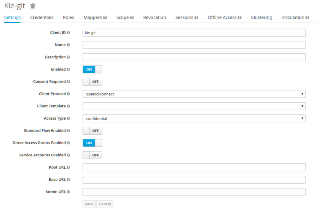
-
Go to the Installation tab in same kie-git client configuration screen and export using the Keycloak OIDC JSON type.
-
Finally copy this generated JSON file into an accessible directory on the server’s file system or add it in the application’s classpath. Use this path value as the keycloak-config-file argument for the above configuration of the org.keycloak.adapters.jaas.DirectAccessGrantsLoginModule login module.
-
More information about Keycloak JAAS Login modules can be found here.
At this point, the internal Git repositories can be cloned by all users authenticated via the Keycloak server:
# Command example:
git clone ssh://admin@localhost:8001/system
5.2.7. Execution server
The KIE Execution Server provides a REST API than can be consumed for any third party clients,. This this section is about how to integration the KIE Execution Server with the Keycloak SSO in order to delegate the third party clients identity management to the SSO server.
Consider the above environment running, so consider having:
-
A Keycloak server running and listening on http://localhost:8180/auth
-
A realm named demo with a client named kie for the jBPM Workbench
-
A jBPM Workbench running at http://localhost:8080/kie-wb-6.4.0-Final
Follow these steps in order to add an execution server into this environment:
-
Create the client for the execution server on Keycloak
-
Install setup and the Execution server ( with the KC client adapter )
5.2.7.1. Create the execution server’s client on Keycloak
As per each execution server is going to be deployed, you have to create a new client on the demo realm in Keycloak.:
-
Go to the KC admin console → Clients → New client
-
Name: kie-execution-server
-
Root URL: http://localhost:8280/
-
Client protocol: openid-connect
-
Access type: confidential ( or public if you want so, but not recommended for production environments)
-
Valid redirect URIs: /kie-server-6.4.0.Final/*
-
Base URL: /kie-server-6.4.0.Final
In this example the admin user already created on previous steps is the one used for the client requests. So ensure that the admin user is member of the role kie-server in order to use the execution server’s remote services. If the role does not exist, create it.
Note: This example considers that the execution server will be configured to run using a port offset of 200, so the HTTP port will be available at localhost:8280.
5.2.7.2. Install and setup the KC adapter on the execution server
At this point, a client named kie-execution-server is ready on the KC server to use from the execution server.
Let’s install, setup and deploy the execution server:
-
Install another Wildfly server to use for the execution server and the KC client adapter as well. You can follow above instructions for the Workbench or follow the official adapters documentation
-
Edit the standalone-full.xml file from the Wildfly server’s configuration path and configure the KC subsystem adapter as:
<secure-deployment name="kie-server-6.4.0.Final.war">
    <realm>demo</realm>
    <realm-public-key>MIGfMA0GCSqGSIb...</realm-public-key>
    <auth-server-url>http://localhost:8180/auth</auth-server-url>
    <ssl-required>external</ssl-required>
    <resource>kie-execution-server</resource>
    <enable-basic-auth>true</enable-basic-auth>
    <credential name="secret">e92ec68d-6177-4239-be05-28ef2f3460ff</credential>
    <principal-attribute>preferred_username</principal-attribute>
</secure-deployment>
Consider your concrete environment settings if different from this example:
-
Secure deployment name → use the name of the execution server war file being deployed
-
Public key → Use the demo realm public key or leave it blank, the server will provide one if so
-
Resource → This time, instead of the kie client used in the WB configuration, use the kie-execution-server client
-
Enable basic auth → Up to you. You can enable Basic auth for third party service consumers
-
Credential → Use the secret key for the kie-execution-server client. You can find it in the Credentialstab of the KC admin console
5.2.7.3. Deploy and run the execution server
Just deploy the execution server in Wildfly using any of the available mechanisms. Run the execution server using this command:
$EXEC_SERVER_HOME/bin/standalone.sh -c standalone-full.xml -Djboss.socket.binding.port-offset=200 -Dorg.kie.server.id=<ID> -Dorg.kie.server.user=<USER> -Dorg.kie.server.pwd=<PWD> -Dorg.kie.server.location=<LOCATION_URL> -Dorg.kie.server.controller=<CONTROLLER_URL> -Dorg.kie.server.controller.user=<CONTROLLER_USER> -Dorg.kie.server.controller.pwd=<CONTOLLER_PASSWORD>Example:
$EXEC_SERVER_HOME/bin/standalone.sh -c standalone-full.xml -Djboss.socket.binding.port-offset=200 -Dorg.kie.server.id=kieserver1 -Dorg.kie.server.user=admin -Dorg.kie.server.pwd=password -Dorg.kie.server.location=http://localhost:8280/kie-server-6.4.0.Final/services/rest/server -Dorg.kie.server.controller=http://localhost:8080/kie-wb-6.4.0.Final/rest/controller -Dorg.kie.server.controller.user=admin -Dorg.kie.server.controller.pwd=passwordmportant note: The users that will consume the execution server remote service endpoints must have the role kie-server assigned. So create and assign this role in the KC admin console for the users that will consume the execution server remote services.
Once up, you can check the server status as (considered using Basic authentication for this request, see nextConsuming remote services for more information):
curl http://admin:password@localhost:8280/kie-server-6.4.0.Final/services/rest/server/5.2.8. Consuming remote services
In order to use the different remote services provided by the Workbench or by an Execution Server, your client must be authenticated on the KC server and have a valid token to perform the requests.
Remember that in order to use the remote services, the authenticated user must have assigned:
-
The role rest-all for using the WB remote services
-
The role kie-server for using the Execution Server remote services
Please ensure necessary roles are created and assigned to the users that will consume the remote services on the Keycloak admin console.
You have two options to consume the different remove service endpoints:
-
Using basic authentication, if the application’s client supports it
-
Using Bearer ( token) based authentication
5.2.8.1. Using basic authentication
If the KC client adapter configuration has the Basic authentication enabled, as proposed in this guide for both WB (step 3.2) and Execution Server, you can avoid the token grant/refresh calls and just call the services as the following examples.
Example for a WB remote repositories endpoint:
curl http://admin:password@localhost:8080/kie-wb-6.4.0.Final/rest/repositoriesExample to check the status for the Execution Server:
curl http://admin:password@localhost:8280/kie-server-6.4.0.Final/services/rest/server/5.2.8.2. Using token based authentication
First step is to create a new client on Keycloak that allows the third party remote service clients to obtain a token. It can be done as:
-
Go to the KC admin console and create a new client using this configuration:
-
Client id: kie-remote
-
Client protocol: openid-connect
-
Access type: public
-
Valid redirect URIs: http://localhost/
-
-
As we are going to manually obtain a token and invoke the service let’s increase the lifespan of tokens slightly. In production access tokens should have a relatively low timeout, ideally less than 5 minutes:
-
Go to the KC admin console
-
Click on your Realm Settings
-
Click on Tokens tab
-
Change the value for Access Token Lifespan to 15 minutes ( That should give us plenty of time to obtain a token and invoke the service before it expires )
-
Once a public client for our remote clients has been created, you can now obtain the token by performing an HTTP request to the KC server’s tokens endpoint. Here is an example for command line:
RESULT=`curl --data "grant_type=password&client_id=kie-remote&username=admin&passwordpassword=<the_client_secret>" http://localhost:8180/auth/realms/demo/protocol/openid-connect/token`TOKEN=`echo $RESULT | sed 's/.*access_token":"//g' | sed 's/".*//g'`At this point, if you echo the $TOKEN it will output the token string obtained from the KC server, that can be now used to authorize further calls to the remote endpoints. For exmple, if you want to check the internal jBPM repositories:
curl -H "Authorization: bearer $TOKEN" http://localhost:8080/kie-wb-6.4.0.Final/rest/repositories6. Workbench High Availability
6.1. VFS clustering
The VFS repositories (usually git repositories) stores all the assets (such as rules, decision tables, process definitions, forms, etc). If that VFS resides on each local server, then it must be kept in sync between all servers of a cluster.
Use Apache Zookeeper and Apache Helix to accomplish this. Zookeeper glues all the parts together. Helix is the cluster management component that registers all cluster details (nodes, resources and the cluster itself). Uberfire (on top of which Workbench is build) uses those 2 components to provide VFS clustering.
To create a VFS cluster:
-
Download Apache Zookeeper and Apache Helix.
-
Install both:
-
Unzip Zookeeper into a directory (
$ZOOKEEPER_HOME). -
In
$ZOOKEEPER_HOME, copyzoo_sample.conftozoo.conf -
Edit
zoo.conf. Adjust the settings if needed. Usually only these 2 properties are relevant:# the directory where the snapshot is stored. dataDir=/tmp/zookeeper # the port at which the clients will connect clientPort=2181 -
Unzip Helix into a directory (
$HELIX_HOME).
-
-
Configure the cluster in Zookeeper:
-
Go to its
bindirectory:$ cd $ZOOKEEPER_HOME/bin -
Start the Zookeeper server:
$ sudo ./zkServer.sh startIf the server fails to start, verify that the
dataDir(as specified inzoo.conf) is accessible. -
To review Zookeeper’s activities, open
zookeeper.out:$ cat $ZOOKEEPER_HOME/bin/zookeeper.out
-
-
Configure the cluster in Helix:
-
Go to its
bindirectory:$ cd $HELIX_HOME/bin -
Create the cluster:
$ ./helix-admin.sh --zkSvr localhost:2181 --addCluster kie-clusterThe
zkSvrvalue must match the used Zookeeper server. The cluster name (kie-cluster) can be changed as needed. -
Add nodes to the cluster:
# Node 1
$ ./helix-admin.sh --zkSvr localhost:2181 --addNode kie-cluster nodeOne:12345
# Node 2
$ ./helix-admin.sh --zkSvr localhost:2181 --addNode kie-cluster nodeTwo:12346
...
Usually the number of nodes a in cluster equal the number of application servers in the cluster. The node names (
nodeOne:12345, …) can be changed as needed.nodeOne:12345is the unique identifier of the node, which will be referenced later on when configuring application servers. It is not a host and port number, but instead it is used to uniquely identify the logical node. -
Add resources to the cluster:
$ ./helix-admin.sh --zkSvr localhost:2181 --addResource kie-cluster vfs-repo 1 LeaderStandby AUTO_REBALANCEThe resource name (
vfs-repo) can be changed as needed. -
Rebalance the cluster to initialize it:
$ ./helix-admin.sh --zkSvr localhost:2181 --rebalance kie-cluster vfs-repo 2 -
Start the Helix controller to manage the cluster:
$ ./run-helix-controller.sh --zkSvr localhost:2181 --cluster kie-cluster 2>&1 > /tmp/controller.log &
-
-
Configure the security domain correctly on the application server. For example on WildFly and JBoss EAP:
-
Edit the file
$JBOSS_HOME/domain/configuration/domain.xml.For simplicity sake, presume we use the default domain configuration which uses the profile
fullthat defines two server nodes as part ofmain-server-group. -
Locate the profile
fulland add a new security domain by copying the other security domain already defined there by default:<security-domain name="kie-ide" cache-type="default"> <authentication> <login-module code="Remoting" flag="optional"> <module-option name="password-stacking" value="useFirstPass"/> </login-module> <login-module code="RealmDirect" flag="required"> <module-option name="password-stacking" value="useFirstPass"/> </login-module> </authentication> </security-domain>The security-domain name is a magic value.
-
-
Configure the system properties for the cluster on the application server. For example on WildFly and JBoss EAP:
-
Edit the file
$JBOSS_HOME/domain/configuration/host.xml. -
Locate the XML elements
serverthat belong to themain-server-groupand add the necessary system property.For example for nodeOne:
<system-properties>
  <property name="jboss.node.name" value="nodeOne" boot-time="false"/>
  <property name="org.uberfire.nio.git.dir" value="/tmp/kie/nodeone" boot-time="false"/>
  <property name="org.uberfire.metadata.index.dir" value="/tmp/kie/nodeone" boot-time="false"/>
  <property name="org.uberfire.cluster.id" value="kie-cluster" boot-time="false"/>
  <property name="org.uberfire.cluster.zk" value="localhost:2181" boot-time="false"/>
  <property name="org.uberfire.cluster.local.id" value="nodeOne_12345" boot-time="false"/>
  <property name="org.uberfire.cluster.vfs.lock" value="vfs-repo" boot-time="false"/>
  <!-- If you're running both nodes on the same machine: -->
  <property name="org.uberfire.nio.git.daemon.port" value="9418" boot-time="false"/>
</system-properties>
And for nodeTwo:
<system-properties>
  <property name="jboss.node.name" value="nodeTwo" boot-time="false"/>
  <property name="org.uberfire.nio.git.dir" value="/tmp/kie/nodetwo" boot-time="false"/>
  <property name="org.uberfire.metadata.index.dir" value="/tmp/kie/nodetwo" boot-time="false"/>
  <property name="org.uberfire.cluster.id" value="kie-cluster" boot-time="false"/>
  <property name="org.uberfire.cluster.zk" value="localhost:2181" boot-time="false"/>
  <property name="org.uberfire.cluster.local.id" value="nodeTwo_12346" boot-time="false"/>
  <property name="org.uberfire.cluster.vfs.lock" value="vfs-repo" boot-time="false"/>
  <!-- If you're running both nodes on the same machine: -->
  <property name="org.uberfire.nio.git.daemon.port" value="9419" boot-time="false"/>
</system-properties>
Make sure the cluster, node and resource names match those configured in Helix.
-
6.2. jBPM clustering
In addition to the information above, jBPM clustering requires additional configuration. See this blog post to configure the database etc correctly.
OptaPlanner Execution Server
The KIE Server is a standalone execution server for rules, planning and workflows.
7. KIE Execution Server
7.1. Overview
The Kie Server is a modular, standalone server component that can be used to instantiate and execute rules and processes. It exposes this functionality via REST, JMS and Java interfaces to client application. It also provides seamless integration with the Kie Workbench.
At its core, the Kie Server is a configurable web application packaged as a WAR file. Distributions are availables for pure web containers (like Tomcat) and for JEE 6 and JEE 7 containers.
Most capabilities on the Kie Server are configurable, and based on the concepts of extensions. Each extension can be enabled/disabled independently, allowing the user to configure the server to its need.
The current version of the Kie Server ships with two default extensions:
-
BRM: provides support for the execution of Business Rules using the Drools rules engine.
-
BPM: provides support for the execution of Business Processes using the jBPM process engine. It supports:
-
process execution
-
task execution
-
assynchronous job execution
-
Both extensions enabled by default, but can be disabled by setting the corresponding property (see configuration chapter for details).
This server was designed to have a low footprint, with minimal memory consumption, and therefore, to be easily deployable on a cloud environment. Each instance of this server can open and instantiate multiple Kie Containers which allows you to execute multiple services in parallel.
7.1.1. Glossary
-
Kie Server: execution server purely focusing on providing runtime environment for both rules and processes. These capabilities are provided by Kie Server Extensions. More capabilities can be added by further extensions (e.g. customer could add his own extensions in case of missing functionality that will then use infrastructure of the KIE Server). A Kie Server instance is a standalone Kie Server executing on a given application server/web container. A Kie Server instantiates and provides support for multiple Kie Containers.
-
Kie Server Extension: a "plugin" for the Kie Server that adds capabilities to the server. The Kie Server ships with two default kie server extensions: BRM and BPM.
-
Kie Container: an in-memory instantiation of a kjar, allowing for the instantiation and usage of its assets (domain models, processes, rules, etc). A Kie Server exposes Kie Containers through a standard API over transport protocols like REST and JMS.
-
Controller: a server-backed REST endpoint that will be responsible for managing KIE Server instances. Such end point must provide following capabilities:
-
respond to connect requests
-
sync all registered containers on the corresponding Kie Server ID
-
respond to disconnect requests
-
-
Kie Server state: currently known state of given Kie Server instance. This is a local storage (by default in file) that maintains the following information:
-
list of registered controllers
-
list of known containers
-
kie server configuration
The server state is persisted upon receival of events like: Kie Container created, Kie Container is disposed, controller accepts registration of Kie Server instance, etc.
-
-
Kie Server ID: an arbitrary assigned identifier to which configurations are assigned. At boot, each Kie Server Instance is assigned an ID, and that ID is matched to a configuration on the controller. The Kie Server Instance fetches and uses that configuration to setup itself.
7.2. Installing the KIE Server
The KIE Server is distributed as a web application archive (WAR) file. The WAR file comes in three different packagings:
-
webc - WAR for ordinary Web (Servlet) containers like Tomcat
-
ee6 - WAR for JavaEE 6 containers like JBoss EAP 6.x
-
ee7 - WAR for JavaEE 7 containers like WildFly 8.x
To install the KIE Execution Server and verify it is running, complete the following steps:
-
Deploy the WAR file into your web container.
-
Create a user with the role of
kie-serveron the container. -
Test that you can access the execution engine by navigating to the endpoint in a browser window:
http://SERVER:PORT/CONTEXT/services/rest/server/. -
When prompted for username/password, type in the username and password that you created in step 2.
-
Once authenticated, you will see an XML response in the form of engine status, similar to this:
Example 1. Sample handshaking server response<response type="SUCCESS" msg="KIE Server info"> <kie-server-info> <version>7.1.0.Final</version> </kie-server-info> </response>
7.2.1. Bootstrap switches
The Kie Server accepts a number of bootstrap switches (system properties) to configure the behaviour of the server. The following is a table of all the supported switches.
| Property | Value | Description | Required |
|---|---|---|---|
org.drools.server.ext.disabled |
boolean (default is "false") |
If true, disables the BRM support (i.e. rules support). |
No |
org.jbpm.server.ext.disabled |
boolean (default is "false") |
If true, disables the BPM support (i.e. processes support) |
No |
org.jbpm.ui.server.ext.disabled |
boolean (default is "false") |
If true, disables the BPM UI support (i.e. processes image support) |
No |
org.optaplanner.server.ext.disabled |
boolean (default is "false") |
If true, disables the BRP support (i.e. planner support) |
No |
org.kie.executor.disabled |
boolean (default is "false") |
If true, disables the BPM job executor support |
No |
org.kie.server.id |
string |
An arbitrary ID to be assigned to this server. If a remote controller is configured, this is the ID under which the server will connect to the controller to fetch the kie container configurations. |
No. If not provided, an ID is automatically generated. |
org.kie.server.user |
string (default is "kieserver") |
User name used to connect with the kieserver from the controller, required when running in managed mode |
No |
org.kie.server.pwd |
string (default is "kieserver1!") |
Password used to connect with the kieserver from the controller, required when running in managed mode |
No |
org.kie.server.controller |
comma separated list of urls |
List of urls to controller REST endpoint. E.g.:
|
Yes when using a controller |
org.kie.server.controller.user |
string (default is "kieserver") |
Username used to connect to the controller REST api |
Yes when using a controller |
org.kie.server.controller.pwd |
string (default is "kieserver1!") |
Password used to connect to the controller REST api |
Yes when using a controller |
org.kie.server.location |
URL location of kie server instance |
The URL used by the controller to call back on this server. E.g.:
|
Yes when using a controller |
org.kie.server.domain |
string |
JAAS LoginContext domain that shall be used to authenticate users when using JMS |
No |
org.kie.server.bypass.auth.user |
boolean (default is "false") |
Allows to bypass the authenticated user for task related operations e.g. queries |
No |
org.kie.server.repo |
valid file system path (default is ".") |
Location on local file system where kie server state files will be stored |
No |
org.kie.server.persistence.ds |
string |
Datasource JNDI name |
Yes when BPM support enabled |
org.kie.server.persistence.tm |
string |
Transaction manager platform for Hibernate properties set |
Yes when BPM support enabled |
org.kie.server.persistence.dialect |
string |
Hibernate dialect to be used |
Yes when BPM support enabled |
org.jbpm.ht.callback |
string |
One of supported callbacks for Task Service (default jaas) |
No |
org.jbpm.ht.custom.callback |
string |
Custom implementation of UserGroupCallback in case org.jbpm.ht.callback was set to ‘custom’ |
No |
kie.maven.settings.custom |
valid file system path |
Location of custom settings.xml for maven configuration |
No |
org.kie.executor.interval |
integer (default is 3) |
Number of time units between polls by executor |
No |
org.kie.executor.pool.size |
integer (default is 1) |
Number of threads in the pool for async work |
No |
org.kie.executor.retry.count |
integer (default is 3) |
Number of retries to handle errors |
No |
org.kie.executor.timeunit |
TimeUnit (default is "SECONDS") |
TimeUnit representing interval |
No |
org.kie.executor.disabled |
boolean (default is "false") |
Disables executor completely |
No |
kie.server.jms.queues.response |
string (default is "queue/KIE.SERVER.RESPONSE") |
JNDI name of response queue for JMS |
No |
org.kie.server.controller.connect |
long (default is 10000) |
Waiting time in milliseconds between repeated attempts to connect kie server to controller when kie server starts up |
No |
org.drools.server.filter.classes |
boolean (default is "false") |
If true, accept only classes which are annotated with @org.kie.api.remote.Remotable or @javax.xml.bind.annotation.XmlRootElement as extra JAXB classes |
No |
|
If you are running both KIE Server and KIE Workbench you must configure KIE Server to use a different Data Source to KIE Workbench using the org.kie.server.persistence.ds property. KIE Workbench uses a jBPM Executor Service that can conflict with KIE Server if they share the same Data Source. |
7.2.2. Installation details for different containers
7.2.2.1. Tomcat 7.x/8.x
-
Download and unzip the Tomcat distribution. Let’s call the root of the distribution
TOMCAT_HOME. This directory is named after the Tomcat version, so for exampleapache-tomcat-7.0.55. -
Download kie-server- -webc.war and place it into
TOMCAT_HOME/webapps. -
Configure user(s) and role(s). Make sure that file
TOMCAT_HOME/conf/tomcat-users.xmlcontains the following username and role definition. You can of course choose different username and password, just make sure that the user has rolekie-server:Example 2. Username and role definition for Tomcat<role rolename="kie-server"/> <user username="serveruser" password="my.s3cr3t.pass" roles="kie-server"/> -
Start the server by running
TOMCAT_HOME/bin/startup.[sh|bat]. You can check out the Tomcat logs inTOMCAT_HOME/logsto see if the application deployed successfully. Please read the table above for the bootstrap switches that can be used to properly configure the instance. For instance:./startup.sh -Dorg.kie.server.id=first-kie-server -Dorg.kie.server.location=http://localhost:8080/kie-server/services/rest/server -
Verify the server is running. Go to
http://SERVER:PORT/CONTEXT/services/rest/server/and type the specified username and password. You should see simple XML message with basic information about the server.
|
You can not leverage the JMS interface when running on Tomcat, or any other Web container. The Web container version of the WAR contains only the REST interface. |
7.2.2.2. WildFly 8.x
-
Download and unzip the WildFly distribution. Let’s call the root of the distribution
WILDFLY_HOME. This directory is named after the WildFly version, so for examplewildfly-8.2.0.Final. -
Download kie-server- -ee7.war and place it into
WILDFLY_HOME/standalone/deployments. -
Configure user(s) and role(s). Execute the following command
WILDFLY_HOME/bin/add-user.[sh|bat] -a -u 'kieserver' -p 'kieserver1!' -ro 'kie-server'. You can of course choose different username and password, just make sure that the user has rolekie-server. -
Start the server by running
WILDFLY_HOME/bin/standalone.[sh|bat] -c standalone-full.xml <bootstrap_switches>. You can check out the standard output or WildFly logs inWILDFLY_HOME/standalone/logsto see if the application deployed successfully. Please read the table above for the bootstrap switches that can be used to properly configure the instance. For instance:./standalone.sh --server-config=standalone-full.xml -Djboss.socket.binding.port-offset=150 -Dorg.kie.server.id=first-kie-server -Dorg.kie.server.location=http://localhost:8230/kie-server/services/rest/server -
Verify the server is running. Go to
http://SERVER:PORT/CONTEXT/services/rest/server/and type the specified username and password. You should see simple XML message with basic information about the server.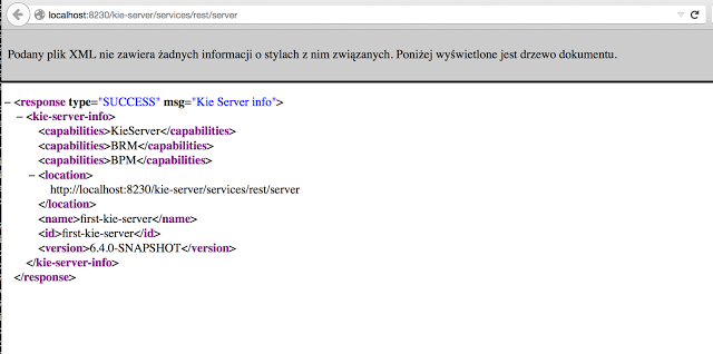
7.3. Kie Server setup
|
Server setup and registration changed significantly from versions 6.2 and before. The following applies only to version 6.3 and forward. |
7.3.1. Managed Kie Server
A managed instance is one that requires a controller to be available to properly startup the Kie Server instance.
A Controller is a component responsible for keeping and managing a Kie Server Configuration in centralized way. Each controller can manager multiple configurations at once and there can be multiple controllers in the environment. Managed KIE Servers can be configured with a list of controllers but will connect to only one at a time.
|
It’s important to mention that even though there can be multiple controllers they should be kept in sync to make sure that regardless which one of them is contacted by KIE Server instance it will provide same set of configuration. |
At startup, if a Kie Server is configured with a list of controllers, it will try succesivelly to connect to each of them until a connection is successfully stablished with one of them. If for any reason a connection can’t be stablished, the server will not start, even if there is local storage available with configuration. This happens by design in order to ensure consistency. For instance, if the Kie Server was down and the configuration has changed, this restriction guarantees that it will run with up to date configuration or not at all.
|
In order to run the Kie Server in standalone mode, without connecting to any controllers, please see "Unmanaged Kie Server". |
The configuration sets, among other things:
-
kie containers to be deployed and started
-
configuration items - currently this is a place holder for further enhancements that will allow remotely configure KIE Execution Server components - timers, persistence, etc
The Controller, besides providing configuration management, is also responsible for overall management of Kie Servers. It provides a REST api that is divided into two parts:
-
the controller itself that is exposed to interact with KIE Execution Server instances
-
an administration API that allows to remotely manage Kie Server instances:
-
add/remove servers
-
add/remove containers to/from the servers
-
start/stop containers on servers
-
The controller deals only with the Kie Server configuration or definition to put it differently. It does not handle any runtime components of KIE Execution Server instances. They are always considered remote to controller. The controller is responsible for persisting the configuration to preserve restarts of the controller itself. It should manage the synchronization as well in case multiple controllers are configured to keep all definitions up to date on all instances of the controller.
By default controller is shipped with Kie Workbench and provides a fully featured management interface (both REST api and UI). It uses underlying git repository as persistent store and thus when GIT repositories are clustered (using Apache Zookeeper and Apache Helix) it will cover the controllers synchronization as well.
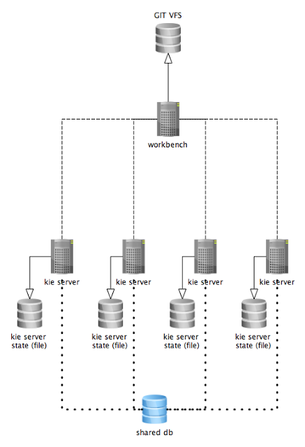
The diagram above illustrates the single controller (workbench) setup with multiple Kie Server instances managed by it.
The diagram bellow illustrates the clustered setup where there are multiple instances of controller synchronized over Zookeeper.
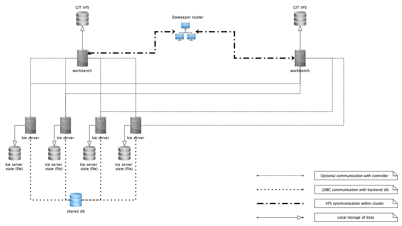
In the above diagram we can see that the Kie Server instances are capable of connecting to any controllers, but they will connect to only one. Each instance will attempt to connect to controller as long as it can reach one. Once connection is established with one of the controllers it will skip the others.
7.3.1.1. Working with managed servers
There are two approaches that users can take when working with managed KIE Server instances:
-
Configuration first: with this approach, a user will start working with the controller (either UI or REST api) and create and configure Kie Server definitions. That consists basically of an identification for the server definition (id and name + optionally version for improved readability) and the configuration for the Kie Containers to run on the server.
-
Registration first: with this approach, the Kie Server instances are started first and auto register themselves on controller. The user then can configure the Kie Containers. This option simply skips the registration step done in the first approach and populates it with server id, name and version directly upon auto registration. There are no other differences between the two approaches.
7.3.2. Unmanaged KIE Execution Server
An unmanaged Kie Server is in turn just a standalone instance, and thus must be configured individually using REST/JMS api from the Kie Server itself. There is no controller involved. The configuration is automatically persisted by the server into a file and that is used as the internal server state, in case of restarts.
The configuration is updated during the following operations:
-
deploy Kie Container
-
undeploy Kie Container
-
start Kie Container
-
stop Kie Container
|
If the Kie Server is restarted, it will try to restablish the same state that was persisted before shutdown. That means that Kie Containers that were running, will be started, but the ones that were stopped/disposed before, will not. |
In most use cases, the Kie Server should be executed in managed mode as that provides some benefits, like a web user interface (if using the workbench as a controller) and some facilities for clustering.
7.4. Creating a Kie Container
Once your Execution Server is registered, you can start adding Kie Containers to it.
Kie Containers are self contained environments that have been provisioned to hold instances of your packaged and deployed rule instances.
-
Start by clicking the \+ icon next to the Execution Server where you want to deploy your Container. This will bring up the New Container screen.
-
If you know the Group Name, Artifact Id and Version (GAV) of your deployed package, then you can enter those details and click the Ok button to select that instance (and provide a name for the Container);
-
If you don’t know these values, you can search KIE Workbench for all packages that can be deployed. Click the Search button without entering any value in the search field (you can narrow your search by entering any term that you know exists in the package that you want to deploy).
INSERT SCREENSHOT HERE
The figure above shows that there are three deployable packages available to be used as containers on the Execution Server. Select the one that you want by clicking the Select button. This will auto-populate the GAV and you can then click the Ok button to use this deployable as the new Container.
-
Enter a name for this Container at the top and then press the Ok button.
The Container name must be unique inside each execution server and must not contain any spaces.
|
Just below the GAV row, you will see an uneditable row that shows you the URL for your Container against which you will be able to execute REST commands. |
7.5. Managing Containers
Containers within the Execution Server can be started, stopped and updated from within KIE Workbench.
7.5.1. Starting a Container
Once registered, a Container is in the 'Stopped' mode. It can be started by first selecting it and then clicking the Start button. You can also select multiple Containers and start them all at the same time.
Once the Container is in the 'Running' mode, a green arrow appears next to it. If there are any errors starting the Container(s), red icons appear next to Containers and the Execution Server that they are deployed on.
You should check the logs of both the Execution Server and the current Business Central to see what the errors are before redeploying the Containers (and possibly the Execution Server).
7.5.2. Stopping and Deleting a Container
Similar to starting a Container, select the Container(s) that you want to stop (or delete) and click the Stop button (which replaces the Start button for that Container once it has entered the 'Running' mode) or the Delete button.
7.5.3. Updating a Container
You can update deployed KieContainers without restarting the Execution Server.
This is useful in cases where the Business Rules change, creating new versions of packages to be provisioned.
You can have multiple versions of the same package provisioned and deployed, each to a different KieContainer.
To update deployments in a KieContainer dynamically, click on the icon next to the Container.
This will open up the Container Info screen.
An example of this screen is shown here:
|
INSERT SCREENSHOT HERE |
The Container Info screen is a useful tool because it not only allows you to see the endpoint for this KieContainer, but it also allows you to either manually or automatically refresh the provision if an update is available.
The update can be manual or automatic:
Manual Update: To manually update a KieContainer, enter the new Version number in the Version box and click on the Update button.
You can of course, update the Group Id or the Artifact Id , if these have changed as well.
Once updated, the Execution server updates the container and shows you the resolved GAV attributes at the bottom of the screen in the Resolved Release Id section.
Automatic Update: If you want a deployed Container to always have the latest version of your deployment without manually editing it, you will need to set the Version property to the value of LATEST and start a Scanner.
This will ensure that the deployed provision always contains the latest version.
The Scanner can be started just once on demand by clicking the Scan Now button or you can start it in the background with scans happening at a specified interval (in milliseconds).You can also set this value to LATEST when you are first creating this deployment.
The Resolved Release
Id in this case will show you the actual, latest version number.
7.6. Kie Server REST API
The Execution Server supports the following commands via the REST API.
Please note the following before using these commands:
-
The base URL for these will remain as the endpoint defined earlier (for example:
http://SERVER:PORT/CONTEXT/services/rest/server/) -
All requests require basic HTTP Authentication for the role kie-server as indicated earlier.
7.6.1. [GET] /
Returns the Execution Server information
<response type="SUCCESS" msg="KIE Server info">
  <kie-server-info>
    <version>6.2.0.redhat-1</version>
  </kie-server-info>
</response>
7.6.2. [POST] /config
Using POST HTTP method, you can execute various commands on the Execution Server. E.g: create-container, list-containers, dispose-container and call-container.
-
CreateContainerCommand
-
GetServerInfoCommand
-
ListContainersCommand
-
CallContainerCommand
-
DisposeContainerCommand
-
GetContainerInfoCommand
-
GetScannerInfoCommand
-
UpdateScannerCommand
-
UpdateReleaseIdCommand
The commands itself can be found in the org.kie.server.api.commands package.
7.6.3. [GET] /containers
Returns a list of containers that have been created on this Execution Server.
<response type="SUCCESS" msg="List of created containers">
  <kie-containers>
    <kie-container container-id="MyProjectContainer" status="STARTED">
      <release-id>
        <artifact-id>Project1</artifact-id>
        <group-id>com.redhat</group-id>
        <version>1.0</version>
      </release-id>
      <resolved-release-id>
        <artifact-id>Project1</artifact-id>
        <group-id>com.redhat</group-id>
        <version>1.0</version>
      </resolved-release-id>
    </kie-container>
  </kie-containers>
</response>
The endpoint supports also filtering based on ReleaseId and container status. Examples:
-
/containers?groupId=org.example- returns only containers with the specified groupId -
/containers?groupId=org.example&artifactId=project1&version=1.0.0.Final- returns only containers with the specifiedReleaseId -
/containers?status=started,failed- returns containers which are either started or failed
7.6.4. [GET] /containers/{id}
Returns the status and information about a particular container.
For example, executing http://SERVER:PORT/CONTEXT/services/rest/server/containers/MyProjectContainer could return the following example container info.
<response type="SUCCESS" msg="Info for container MyProjectContainer">
<kie-container container-id="MyProjectContainer" status="STARTED">
<release-id>
<artifact-id>Project1</artifact-id>
<group-id>com.redhat</group-id>
<version>1.0</version>
</release-id>
<resolved-release-id>
<artifact-id>Project1</artifact-id>
<group-id>com.redhat</group-id>
<version>1.0</version>
</resolved-release-id>
</kie-container>
</response>7.6.5. [PUT] /containers/{id}
Allows you to create a new Container in the Execution Server.
For example, to create a Container with the id of MyRESTContainer the complete endpoint will be: http://SERVER:PORT/CONTEXT/services/rest/server/containers/MyRESTContainer.
An example of request is:
<kie-container container-id="MyRESTContainer">
  <release-id>
    <artifact-id>Project1</artifact-id>
    <group-id>com.redhat</group-id>
    <version>1.0</version>
  </release-id>
</kie-container>
And the response from the server, if successful, would be be:
<response type="SUCCESS" msg="Container MyRESTContainer successfully deployed with module com.redhat:Project1:1.0">
  <kie-container container-id="MyProjectContainer" status="STARTED">
    <release-id>
      <artifact-id>Project1</artifact-id>
      <group-id>com.redhat</group-id>
      <version>1.0</version>
    </release-id>
    <resolved-release-id>
      <artifact-id>Project1</artifact-id>
      <group-id>com.redhat</group-id>
      <version>1.0</version>
    </resolved-release-id>
  </kie-container>
</response>
7.6.6. [DELETE] /containers/{id}
Disposes the Container specified by the id.
For example, executing http://SERVER:PORT/CONTEXT/services/rest/server/containers/MyProjectContainer using the DELETE HTTP method will return the following server response:
<response type="SUCCESS" msg="Container MyProjectContainer successfully disposed."/>7.6.7. [POST] /containers/instances/{id}
Executes operations and commands against the specified Container.
You can send commands to this Container in the body of the POST request.
For example, to fire all rules for Container with id MyRESTContainer (http://SERVER:PORT/CONTEXT/services/rest/server/containers/instances/MyRESTContainer), you would send the fire-all-rules command to it as shown below (in the body of the POST request):
<fire-all-rules/>Following is the list of supported commands:
-
AgendaGroupSetFocusCommand
-
ClearActivationGroupCommand
-
ClearAgendaCommand
-
ClearAgendaGroupCommand
-
ClearRuleFlowGroupCommand
-
DeleteCommand
-
InsertObjectCommand
-
ModifyCommand
-
GetObjectCommand
-
InsertElementsCommand
-
FireAllRulesCommand
-
QueryCommand
-
SetGlobalCommand
-
GetGlobalCommand
-
GetObjectsCommand
-
BatchExecutionCommand
These commands can be found in the org.drools.core.command.runtime package.
7.6.8. [GET] /containers/{id}/release-id
Returns the full release id for the Container specified by the id.
<response type="SUCCESS" msg="ReleaseId for container MyProjectContainer">
<release-id>
<artifact-id>Project1</artifact-id>
<group-id>com.redhat</group-id>
<version>1.0</version>
</release-id>
</response>7.6.9. [POST] /containers/{id}/release-id
Allows you to update the release id of the container deployment. Send the new complete release id to the Server.
<release-id>
  <artifact-id>Project1</artifact-id>
  <group-id>com.redhat</group-id>
  <version>1.1</version>
</release-id>
The Server will respond with a success or error message, similar to the one below:
<response type="SUCCESS" msg="Release id successfully updated.">
  <release-id>
    <artifact-id>Project1</artifact-id>
    <group-id>com.redhat</group-id>
    <version>1.0</version>
  </release-id>
</response>
7.6.10. [GET] /containers/{id}/scanner
Returns information about the scanner for this Container’s automatic updates.
<response type="SUCCESS" msg="Scanner info successfully retrieved">
  <kie-scanner status="DISPOSED"/>
</response>
7.6.11. [POST] /containers/{id}/scanner
Allows you to start or stop a scanner that controls polling for updated Container deployments.
To start the scanner, send a request similar to: http://SERVER:PORT/CONTEXT/services/rest/server/containers/{container-id}/scanner with the following POST data.
<kie-scanner status="STARTED" poll-interval="2000"/>The poll-interval attribute is in milliseconds. The response from the server will be similar to:
<response type="SUCCESS" msg="Kie scanner successfully created.">
  <kie-scanner status="STARTED"/>
</response>
To stop the Scanner, replace the status with DISPOSED and remove the poll-interval attribute.
7.7. OptaPlanner REST API
The Kie Server supports the following Planner REST APIs. As usual, all these APIs are also available through JMS and the Java client API. Please also note:
-
The base URL for these will remain as the endpoint defined earlier (for example
http://SERVER:PORT/CONTEXT/services/rest/server/). -
All requests require basic HTTP Authentication for the role kie-server as indicated earlier.
-
To get a specific marshalling format, add the HTTP headers
Content-Typeand optionalX-KIE-ContentTypein the HTTP request. For example:Content-Type: application/xml X-KIE-ContentType: xstream
|
|
The example requests and responses used below presume that a Kie Container is built using the optacloud example of Planner Workbench, by calling a PUT on /services/rest/server/containers/optacloud-kiecontainer-1 with this content:
<kie-container container-id="optacloud-kiecontainer-1">
  <release-id>
    <group-id>opta</group-id>
    <artifact-id>optacloud</artifact-id>
    <version>1.0.0</version>
  </release-id>
</kie-container>
7.7.1. [GET] /containers
Returns the list of created containers.
<response type="SUCCESS" msg="List of created containers">
  <result class="kie-containers">
    <kie-container>
      <container-id>optacloud-kiecontainer-1</container-id>
        <release-id>
          <group-id>optacloud</group-id>
          <artifact-id>optacloud</artifact-id>
          <version>1.0.0</version>
        </release-id>
        <resolved-release-id>
          <group-id>optacloud</group-id>
          <artifact-id>optacloud</artifact-id>
          <version>1.0.0</version>
        </resolved-release-id>
        <status>STARTED</status>
        <scanner>
          <status>DISPOSED</status>
        </scanner>
    </kie-container>
  </result>
</response>
7.7.2. [PUT] /containers/{containerId}/solvers/{solverId}
Creates a new solver with the given {solverId} in the container {containerId}.
The request’s body is a marshalled SolverInstance entity that must specify the solver configuration file.
The following is an example of the request and the corresponding response.
<solver-instance>
  <solver-config-file>optacloud/optacloud/cloudSolverConfig.solver.xml</solver-config-file>
</solver-instance><solver-instance>
<container-id>optacloud-kiecontainer-1</container-id>
<solver-id>solver1</solver-id>
<solver-config-file>optacloud/optacloud/cloudSolverConfig.solver.xml</solver-config-file>
<status>NOT_SOLVING</status>
<score />
</solver-instance>7.7.3. [GET] /containers/{containerId}/solvers
Returns the list of solvers created in the container.
<org.kie.server.api.model.instance.SolverInstanceList>
<solvers>
<solver-instance>
<container-id>optacloud-kiecontainer-1</container-id>
<solver-id>solver2</solver-id>
<solver-config-file>optacloud/optacloud/cloudSolverConfig2.solver.xml</solver-config-file>
<status>NOT_SOLVING</status>
<score />
</solver-instance>
<solver-instance>
  <container-id>optacloud-kiecontainer-1</container-id>
  <solver-id>solver1</solver-id>
  <solver-config-file>optacloud/optacloud/cloudSolverConfig.solver.xml</solver-config-file>
  <status>NOT_SOLVING</status>
  <score />
</solver-instance>
</solvers>
</org.kie.server.api.model.instance.SolverInstanceList>7.7.4. [GET] /containers/{containerId}/solvers/{solverId}
Returns the current state of the solver {solverId} in container {containerId}.
<solver-instance>
  <container-id>optacloud-kiecontainer-1</container-id>
  <solver-id>solver1</solver-id>
  <solver-config-file>optacloud/optacloud/cloudSolverConfig.solver.xml</solver-config-file>
  <status>NOT_SOLVING</status>
  <score />
</solver-instance>
7.7.5. [POST] /containers/{containerId}/solvers/{solverId}/state/solving
Starts the solver {solverId} in container {containerId} if it is not executing yet.
The request’s body is a marshalled PlanningSolution to be optimized.
The following is an example to solve the OptaCloud problem with 2 computers and 6 processes. The solver runs asynchronously. Send a request to the bestsolution URL to get the best solution.
<optacloud.optacloud.CloudSolution id="1">
  <computerList id="2">
    <optacloud.optacloud.Computer id="3">
      <cpuPower>24</cpuPower>
      <memory>96</memory>
      <networkBandwidth>16</networkBandwidth>
      <cost>4800</cost>
    </optacloud.optacloud.Computer>
    <optacloud.optacloud.Computer id="4">
      <cpuPower>6</cpuPower>
      <memory>4</memory>
      <networkBandwidth>6</networkBandwidth>
      <cost>660</cost>
    </optacloud.optacloud.Computer>
  </computerList>
  <processList id="5">
    <optacloud.optacloud.Process id="6">
      <requiredCpuPower>1</requiredCpuPower>
      <requiredMemory>1</requiredMemory>
      <requiredNetworkBandwidth>1</requiredNetworkBandwidth>
    </optacloud.optacloud.Process>
    <optacloud.optacloud.Process id="7">
      <requiredCpuPower>3</requiredCpuPower>
      <requiredMemory>6</requiredMemory>
      <requiredNetworkBandwidth>1</requiredNetworkBandwidth>
    </optacloud.optacloud.Process>
    <optacloud.optacloud.Process id="8">
      <requiredCpuPower>1</requiredCpuPower>
      <requiredMemory>1</requiredMemory>
      <requiredNetworkBandwidth>3</requiredNetworkBandwidth>
    </optacloud.optacloud.Process>
    <optacloud.optacloud.Process id="9">
      <requiredCpuPower>1</requiredCpuPower>
      <requiredMemory>2</requiredMemory>
      <requiredNetworkBandwidth>11</requiredNetworkBandwidth>
    </optacloud.optacloud.Process>
    <optacloud.optacloud.Process id="10">
      <requiredCpuPower>1</requiredCpuPower>
      <requiredMemory>1</requiredMemory>
      <requiredNetworkBandwidth>1</requiredNetworkBandwidth>
    </optacloud.optacloud.Process>
    <optacloud.optacloud.Process id="11">
      <requiredCpuPower>1</requiredCpuPower>
      <requiredMemory>1</requiredMemory>
      <requiredNetworkBandwidth>5</requiredNetworkBandwidth>
    </optacloud.optacloud.Process>
  </processList>
</optacloud.optacloud.CloudSolution><?xml version="1.0" encoding="UTF-8" standalone="yes" ?>
<cloudSolution>
<computerList>
<cost>4800</cost>
<cpuPower>24</cpuPower>
<memory>96</memory>
<networkBandwidth>16</networkBandwidth>
</computerList>
<computerList>
<cost>660</cost>
<cpuPower>6</cpuPower>
<memory>4</memory>
<networkBandwidth>6</networkBandwidth>
</computerList>
<processList>
<requiredCpuPower>1</requiredCpuPower>
<requiredMemory>1</requiredMemory>
<requiredNetworkBandwidth>1</requiredNetworkBandwidth>
</processList>
<processList>
<requiredCpuPower>3</requiredCpuPower>
<requiredMemory>6</requiredMemory>
<requiredNetworkBandwidth>1</requiredNetworkBandwidth>
</processList>
<processList>
<requiredCpuPower>1</requiredCpuPower>
<requiredMemory>1</requiredMemory>
<requiredNetworkBandwidth>3</requiredNetworkBandwidth>
</processList>
<processList>
<requiredCpuPower>1</requiredCpuPower>
<requiredMemory>2</requiredMemory>
<requiredNetworkBandwidth>11</requiredNetworkBandwidth>
</processList>
<processList>
<requiredCpuPower>1</requiredCpuPower>
<requiredMemory>1</requiredMemory>
<requiredNetworkBandwidth>1</requiredNetworkBandwidth>
</processList>
<processList>
<requiredCpuPower>1</requiredCpuPower>
<requiredMemory>1</requiredMemory>
<requiredNetworkBandwidth>5</requiredNetworkBandwidth>
</processList>
</cloudSolution>{
"optacloud.optacloud.CloudSolution": {
"computerList": [
{
"cpuPower": 24,
"memory": 96,
"networkBandwidth": 16,
"cost": 4800
},
{
"cpuPower": 6,
"memory": 4,
"networkBandwidth": 6,
"cost": 660
}
],
"processList": [
{
"requiredCpuPower": 1,
"requiredMemory": 1,
"requiredNetworkBandwidth": 1
},
{
"requiredCpuPower": 3,
"requiredMemory": 6,
"requiredNetworkBandwidth": 1
},
{
"requiredCpuPower": 1,
"requiredMemory": 1,
"requiredNetworkBandwidth": 3
},
{
"requiredCpuPower": 1,
"requiredMemory": 2,
"requiredNetworkBandwidth": 11
},
{
"requiredCpuPower": 1,
"requiredMemory": 1,
"requiredNetworkBandwidth": 1
},
{
"requiredCpuPower": 1,
"requiredMemory": 1,
"requiredNetworkBandwidth": 5
}
]
}
}7.7.6. [POST] /containers/{containerId}/solvers/{solverId}/state/terminating-early
Requests the solver to terminate early, if it is running. This doesn’t delete the solver, the best solution can still be retrieved.
7.7.7. [GET] /containers/{containerId}/solvers/{solverId}/bestsolution
Returns the best solution found at the time the request is made.
If the solver hasn’t terminated yet (so the status field is still SOLVING), it will return the best solution found up to then, but later calls can return a better solution.
<solver-instance>
  <container-id>optacloud-kiecontainer-1</container-id>
  <solver-id>solver1</solver-id>
  <solver-config-file>optacloud/optacloud/cloudSolverConfig.solver.xml</solver-config-file>
  <status>NOT_SOLVING</status>
  <score scoreClass="org.optaplanner.core.api.score.buildin.hardsoft.HardSoftScore">0hard/-5460soft</score>
  <best-solution class="optacloud.optacloud.CloudSolution">
    <computerList>
      <optacloud.optacloud.Computer>
        <cpuPower>24</cpuPower>
        <memory>96</memory>
        <networkBandwidth>16</networkBandwidth>
        <cost>4800</cost>
      </optacloud.optacloud.Computer>
      <optacloud.optacloud.Computer>
        <cpuPower>6</cpuPower>
        <memory>4</memory>
        <networkBandwidth>6</networkBandwidth>
        <cost>660</cost>
      </optacloud.optacloud.Computer>
    </computerList>
    <processList>
      <optacloud.optacloud.Process>
        <requiredCpuPower>1</requiredCpuPower>
        <requiredMemory>1</requiredMemory>
        <requiredNetworkBandwidth>1</requiredNetworkBandwidth>
        <computer reference="../../../computerList/optacloud.optacloud.Computer[2]"/>
      </optacloud.optacloud.Process>
      <optacloud.optacloud.Process>
        <requiredCpuPower>3</requiredCpuPower>
        <requiredMemory>6</requiredMemory>
        <requiredNetworkBandwidth>1</requiredNetworkBandwidth>
        <computer reference="../../../computerList/optacloud.optacloud.Computer"/>
      </optacloud.optacloud.Process>
      <optacloud.optacloud.Process>
        <requiredCpuPower>1</requiredCpuPower>
        <requiredMemory>1</requiredMemory>
        <requiredNetworkBandwidth>3</requiredNetworkBandwidth>
        <computer reference="../../../computerList/optacloud.optacloud.Computer"/>
      </optacloud.optacloud.Process>
      <optacloud.optacloud.Process>
        <requiredCpuPower>1</requiredCpuPower>
        <requiredMemory>2</requiredMemory>
        <requiredNetworkBandwidth>11</requiredNetworkBandwidth>
        <computer reference="../../../computerList/optacloud.optacloud.Computer"/>
      </optacloud.optacloud.Process>
      <optacloud.optacloud.Process>
        <requiredCpuPower>1</requiredCpuPower>
        <requiredMemory>1</requiredMemory>
        <requiredNetworkBandwidth>1</requiredNetworkBandwidth>
        <computer reference="../../../computerList/optacloud.optacloud.Computer"/>
      </optacloud.optacloud.Process>
      <optacloud.optacloud.Process>
        <requiredCpuPower>1</requiredCpuPower>
        <requiredMemory>1</requiredMemory>
        <requiredNetworkBandwidth>5</requiredNetworkBandwidth>
        <computer reference="../../../computerList/optacloud.optacloud.Computer[2]"/>
      </optacloud.optacloud.Process>
    </processList>
    <score>0hard/-5460soft</score>
  </best-solution>
</solver-instance>
7.7.8. [DELETE] /containers/{containerId}/solvers/{solverId}
Disposes the solver {solverId} in container {containerId}.
If it hasn’t terminated yet, it terminates it first.
7.8. Controller REST API
When you have Managed Kie Server setup, you need to manage Kie Servers and Containers via a Controller. Generally, it’s done by workbench UI but you may also use Controller REST API.
-
The controller base URL is provided by kie-wb war deployment, which would be the same as org.kie.server.controller property. (for example:
http://localhost:8080/kie-wb/rest/controller) -
All requests require basic HTTP Authentication for the role kie-server as indicated earlier.
7.8.1. [GET] /management/servers
Returns a list of Kie Server templates
<?xml version="1.0" encoding="UTF-8" standalone="yes"?>
<server-template-list>
    <server-template>
        <server-id>demo</server-id>
        <server-name>demo</server-name>
        <container-specs>
            <container-id>hr</container-id>
            <container-name>hr</container-name>
            <server-template-key>
                <server-id>demo</server-id>
            </server-template-key>
            <release-id>
                <artifact-id>HR</artifact-id>
                <group-id>org.jbpm</group-id>
                <version>1.0</version>
            </release-id>
            <configs>
                <entry>
                    <key>RULE</key>
                    <value xsi:type="ruleConfig" xmlns:xsi="http://www.w3.org/2001/XMLSchema-instance">
                        <scanner-status>STOPPED</scanner-status>
                    </value>
                </entry>
                <entry>
                    <key>PROCESS</key>
                    <value xsi:type="processConfig" xmlns:xsi="http://www.w3.org/2001/XMLSchema-instance">
                        <strategy>Singleton</strategy>
                        <kie-base-name></kie-base-name>
                        <kie-session-name></kie-session-name>
                        <merge-mode>Merge Collections</merge-mode>
                    </value>
                </entry>
            </configs>
            <status>STARTED</status>
        </container-specs>
        <configs/>
        <server-instances>
            <server-instance-id>demo@localhost:8230</server-instance-id>
            <server-name>demo@localhost:8230</server-name>
            <server-template-id>demo</server-template-id>
            <server-url>http://localhost:8230/kie-server/services/rest/server</server-url>
        </server-instances>
        <capabilities>RULE</capabilities>
        <capabilities>PROCESS</capabilities>
        <capabilities>PLANNING</capabilities>
    </server-template>
</server-template-list>
7.8.2. [GET] /management/server/{id}
Returns a Kie Server template
<?xml version="1.0" encoding="UTF-8" standalone="yes"?>
<server-template-details>
    <server-id>product-demo</server-id>
    <server-name>product-demo</server-name>
    <container-specs>
        <container-id>hr</container-id>
        <container-name>hr</container-name>
        <server-template-key>
            <server-id>demo</server-id>
        </server-template-key>
        <release-id>
            <artifact-id>HR</artifact-id>
            <group-id>org.jbpm</group-id>
            <version>1.0</version>
        </release-id>
        <configs>
            <entry>
                <key>RULE</key>
                <value xsi:type="ruleConfig" xmlns:xsi="http://www.w3.org/2001/XMLSchema-instance">
                    <scanner-status>STOPPED</scanner-status>
                </value>
            </entry>
            <entry>
                <key>PROCESS</key>
                <value xsi:type="processConfig" xmlns:xsi="http://www.w3.org/2001/XMLSchema-instance">
                    <strategy>Singleton</strategy>
                    <kie-base-name></kie-base-name>
                    <kie-session-name></kie-session-name>
                    <merge-mode>Merge Collections</merge-mode>
                </value>
            </entry>
        </configs>
        <status>STARTED</status>
    </container-specs>
    <configs/>
    <server-instances>
        <server-instance-id>demo@localhost:8230</server-instance-id>
        <server-name>demo@localhost:8230</server-name>
        <server-template-id>demo</server-template-id>
        <server-url>http://localhost:8230/kie-server/services/rest/server</server-url>
    </server-instances>
    <capabilities>RULE</capabilities>
    <capabilities>PROCESS</capabilities>
    <capabilities>PLANNING</capabilities>
</server-template-details>
7.8.3. [PUT] /management/server/{id}
Creates a new Kie Server template with the specified id
<?xml version="1.0" encoding="UTF-8" standalone="yes"?>
<server-template-details>
    <server-id>test-demo</server-id>
    <server-name>test-demo</server-name>
    <configs/>
    <capabilities>RULE</capabilities>
    <capabilities>PROCESS</capabilities>
    <capabilities>PLANNING</capabilities>
</server-template-details>
7.8.4. [DELETE] /management/server/{id}
Deletes a Kie Server template with the specified id
7.8.5. [GET] /management/server/{id}/containers
Returns all containers on given server
<?xml version="1.0" encoding="UTF-8" standalone="yes"?>
<container-spec-list>
    <container-spec>
        <container-id>hr</container-id>
        <container-name>hr</container-name>
        <server-template-key>
            <server-id>demo</server-id>
        </server-template-key>
        <release-id>
            <artifact-id>HR</artifact-id>
            <group-id>org.jbpm</group-id>
            <version>1.0</version>
        </release-id>
        <configs>
            <entry>
                <key>RULE</key>
                <value xsi:type="ruleConfig" xmlns:xsi="http://www.w3.org/2001/XMLSchema-instance">
                    <scanner-status>STOPPED</scanner-status>
                </value>
            </entry>
            <entry>
                <key>PROCESS</key>
                <value xsi:type="processConfig" xmlns:xsi="http://www.w3.org/2001/XMLSchema-instance">
                    <strategy>Singleton</strategy>
                    <kie-base-name></kie-base-name>
                    <kie-session-name></kie-session-name>
                    <merge-mode>Merge Collections</merge-mode>
                </value>
            </entry>
        </configs>
        <status>STARTED</status>
    </container-spec>
</container-spec-list>
7.8.6. [GET] /management/server/{id}/containers/{containerId}
Returns the Container information including its release id and configuration
<?xml version="1.0" encoding="UTF-8" standalone="yes"?>
<container-spec-details>
    <container-id>hr</container-id>
    <container-name>hr</container-name>
    <server-template-key>
        <server-id>demo</server-id>
    </server-template-key>
    <release-id>
        <artifact-id>HR</artifact-id>
        <group-id>org.jbpm</group-id>
        <version>1.0</version>
    </release-id>
    <configs>
        <entry>
            <key>PROCESS</key>
            <value xsi:type="processConfig" xmlns:xsi="http://www.w3.org/2001/XMLSchema-instance">
                <strategy>Singleton</strategy>
                <kie-base-name></kie-base-name>
                <kie-session-name></kie-session-name>
                <merge-mode>Merge Collections</merge-mode>
            </value>
        </entry>
        <entry>
            <key>RULE</key>
            <value xsi:type="ruleConfig" xmlns:xsi="http://www.w3.org/2001/XMLSchema-instance">
                <scanner-status>STOPPED</scanner-status>
            </value>
        </entry>
    </configs>
    <status>STARTED</status>
</container-spec-details>
7.8.7. [PUT] /management/server/{id}/containers/{containerId}
Creates a new Container with the specified containerId and the given release id and optionally configuration
<?xml version="1.0" encoding="UTF-8" standalone="yes"?>
<container-spec-details>
    <container-id>hr</container-id>
    <container-name>hr</container-name>
    <server-template-key>
        <server-id>demo</server-id>
    </server-template-key>
    <release-id>
        <artifact-id>HR</artifact-id>
        <group-id>org.jbpm</group-id>
        <version>1.0</version>
    </release-id>
    <configs>
        <entry>
            <key>PROCESS</key>
            <value xsi:type="processConfig" xmlns:xsi="http://www.w3.org/2001/XMLSchema-instance">
                <strategy>Singleton</strategy>
                <kie-base-name></kie-base-name>
                <kie-session-name></kie-session-name>
                <merge-mode>Merge Collections</merge-mode>
            </value>
        </entry>
        <entry>
            <key>RULE</key>
            <value xsi:type="ruleConfig" xmlns:xsi="http://www.w3.org/2001/XMLSchema-instance">
                <scanner-status>STOPPED</scanner-status>
            </value>
        </entry>
    </configs>
    <status>STARTED</status>
</container-spec-details
7.8.8. [DELETE] /management/server/{id}/containers/{containerId}
Disposes a Container with the specified containerId
7.8.9. [POST] /management/server/{id}/containers/{containerId}/status/started
Starts the Container. No request body required
7.8.10. [POST] /management/server/{id}/containers/{containerId}/status/stopped
Stops the Container. No request body required
7.9. Kie Server Java Client API
The Kie Server has a great Java API to wrap REST or JMS requests to be sent to the server. In this section we will explore some of the possibilities of this API.
7.9.1. Maven Configuration
if you are a Maven user, make sure you have at least the following dependencies in the project’s pom.xml
<dependency>
  <groupId>org.kie.server</groupId>
  <artifactId>kie-server-client</artifactId>
  <version>${kie.api.version}</version>
</dependency>
<!-- Logging -->
<dependency>
  <groupId>ch.qos.logback</groupId>
  <artifactId>logback-classic</artifactId>
  <version>1.1.2</version>
</dependency>
<!-- Drools Commands -->
<dependency>
  <groupId>org.drools</groupId>
  <artifactId>drools-compiler</artifactId>
  <scope>runtime</scope>
  <version>${kie.api.version}</version>
</dependency>
The version kie.api.version depends on the Kie Server version you are using. For jBPM 6.3, for example, you can use 6.3.1-SNAPSHOT.
7.9.2. Client Configuration
The client requires a configuration object where you set most of the server communication aspects, such as the protocol (REST and JMS) credentials and the payload format (XStream, JAXB and JSON are the supported formats at the moment). The first thing to do is create your configuration then create the KieServicesClient object, the entry point for starting the server communication.
See the source below where we use a REST client configuration:
import org.kie.server.api.marshalling.MarshallingFormat;
import org.kie.server.client.KieServicesClient;
import org.kie.server.client.KieServicesConfiguration;
import org.kie.server.client.KieServicesFactory;

public class DecisionServerTest {

    private static final String URL = "http://localhost:8080/kie-server/services/rest/server";
    private static final String USER = "kieserver";
    private static final String PASSWORD = "kieserver1!";

    private static final MarshallingFormat FORMAT = MarshallingFormat.JSON;

    private KieServicesConfiguration conf;
    private KieServicesClient kieServicesClient;

    public void initialize() {
        conf = KieServicesFactory.newRestConfiguration(URL, USER, PASSWORD);
        conf.setMarshallingFormat(FORMAT);
        kieServicesClient = KieServicesFactory.newKieServicesClient(conf);
    }
7.9.2.1. JMS interaction patterns
In version 6.5 KIE Server Client JMS integration has been enhanced with possibility to use various interaction patterns. Currently available are:
-
request reply (which is the default) - that makes the JMS integration synchronous - it blocks client until it gets the response back - not suited for JMS transactional use case
-
fire and forget - makes the integration one way only, suitable for notification like integration with kie server - makes perfect fit for transactional JMS delivery - deliver message to kie server only if transaction that ckie server client was invoked in was committed successfully
-
async with callback - allows to not block a client after sending message to kie server and receive response asynchronously - can be integrated with transactional JMS delivery
Response handlers can be either set globally - when KieServicesConfiguration is created or it can be changed on runtime on individual client instances (like RuleServiceClient, ProcessServicesClient, etc)
While 'fire and forget' and 'request reply' patterns do not require any additional configuration 'async with callback' does. And the main thing is actually the callback. KIE Server CLient comes with one out of the box - BlockingResponseCallback that provides basic support backed by blocking queue internally. Size of the queue is confgurable and thus allow receiving multiple messages, though intention of this callback is that it will only receive one message at a time - so it’s like one message (request) and then one response per client interaction.
| Kie Server Client when switching response handler is not thread safe, meaning change of the handler will affect all threads using same client instance. So in case of dynamic changes of the handler it’s recommended to use separate client instances. A good approach is to maintain set of clients that use dedicated response handler and then use these clients dependeing on which handler is required. |
Example:
client 1 will use fire and forget while client 2 will use request reply. So client 1 can be used to start processes and client 2 can be used to query for user tasks.
Users can provide their own callbacks by implementing org.kie.server.client.jms.ResponseCallback interface.
Configuration
Global JMS configuration
----
InitialContext context = ...;
Queue requestQueue = (Queue) context.lookup("jms/queue/KIE.SERVER.REQUEST"));
Queue responseQueue = (Queue) context.lookup("jms/queue/KIE.SERVER.RESPONSE");
ConnectionFactory connectionFactory = (ConnectionFactory) context.lookup("jms/RemoteConnectionFactory");
KieServicesConfiguration jmsConfiguration = KieServicesFactory.newJMSConfiguration( connectionFactory, requestQueue, responseQueue, "user", "password");
// here you set response handler globally
jmsConfiguration.setResponseHandler(new FireAndForgetResponseHandler());
----
Alternatively, might be actually more common, is to set the handler on individual clients before they are used
Per client configuration
----
ProcessServiceClient processClient = client.getServicesClient(ProcessServicesClient.class);
// change response handler for processClient others are not affected
processClient.setResponseHandler(new FireAndForgetResponseHandler());
---
7.9.3. Server Response
All the service responses are represented by the object org.kie.server.api.model.ServiceResponse<T> where T is the type of the payload.
It has the following attributes:
String msg: The response message;
org.kie.server.api.model.ServiceResponse.ResponseType type: the response type enum, which can be SUCCESS or FAILURE;
T result: The actual payload of the response, the requested object.
Notice that this is the same object returned if you are using REST or JMS, in another words it is agnostic to protocol.
7.9.4. Server Capabilities
Decision Server initially only supported rules execution, starting in version 6.3 it started supporting business process execution.
To know what exactly your server support, you can list the server capabilities by accessing the object org.kie.server.api.model.KieServerInfo**using the client:
public void listCapabilities() {
    KieServerInfo serverInfo = kieServicesClient.getServerInfo().getResult();
    System.out.print("Server capabilities:");
    for(String capability: serverInfo.getCapabilities()) {
        System.out.print(" " + capability);
    }
    System.out.println();
}
If the server supports rules and process, the following should be printed when you run the code above:
Server capabilities: BRM KieServer BPM
7.9.5. Kie Containers
If you want to publish a kjar to receive requests, you must publish it in a container.
The container is represented in the client by the object org.kie.server.api.model.KieContainerResource, and a list of resources is org.kie.server.api.model.KieContainerResourceList.
Here’s an example of how to print a list of containers:
public void listContainers() {
    KieContainerResourceList containersList = kieServicesClient.listContainers().getResult();
    List<KieContainerResource> kieContainers = containersList.getContainers();
    System.out.println("Available containers: ");
    for (KieContainerResource container : kieContainers) {
        System.out.println("\t" + container.getContainerId() + " (" + container.getReleaseId() + ")");
    }
}
It is also possible to list the containers based on specific ReleaseId (and its individual parts) or status:
public void listContainersWithFilter() {
    // the following filter will match only containers with ReleaseId "org.example:contatner:1.0.0.Final" and status FAILED
    KieContainerResourceFilter filter = new KieContainerResourceFilter.Builder()
            .releaseId("org.example", "container", "1.0.0.Final")
            .status(KieContainerStatus.FAILED)
            .build();
    KieContainerResourceList containersList = kieServicesClient.listContainers(filter).getResult();
    List<KieContainerResource> kieContainers = containersList.getContainers();
    System.out.println("Available containers: ");
    for (KieContainerResource container : kieContainers) {
        System.out.println("\t" + container.getContainerId() + " (" + container.getReleaseId() + ")");
    }
}
7.9.6. Managing Containers
You can use the client to dispose and create containers. If you dispose a containers, a ServiceResponse will be returned with Void payload(no payload) and if you create it, the KieContainerResource object itself will be returned in the response. Sample code:
public void disposeAndCreateContainer() {
    System.out.println("== Disposing and creating containers ==");
    List<KieContainerResource> kieContainers = kieServicesClient.listContainers().getResult().getContainers();
    if (kieContainers.size() == 0) {
        System.out.println("No containers available...");
        return;
    }
    KieContainerResource container = kieContainers.get(0);
    String containerId = container.getContainerId();
    ServiceResponse<Void> responseDispose = kieServicesClient.disposeContainer(containerId);
    if (responseDispose.getType() == ResponseType.FAILURE) {
        System.out.println("Error disposing " + containerId + ". Message: ");
        System.out.println(responseDispose.getMsg());
        return;
    }
    System.out.println("Success Disposing container " + containerId);
    System.out.println("Trying to recreate the container...");
    ServiceResponse<KieContainerResource> createResponse = kieServicesClient.createContainer(containerId, container);
    if(createResponse.getType() == ResponseType.FAILURE) {
        System.out.println("Error creating " + containerId + ". Message: ");
        System.out.println(responseDispose.getMsg());
        return;
    }
     System.out.println("Container recreated with success!");
}
7.9.7. Available Clients for the Decision Server
The KieServicesClient is also the entry point for others clients to perform specific operations, such as send BRMS commands and manage processes.
Currently from the KieServicesClient you can have access to the following services available in org.kie.server.client package:
-
JobServicesClient: This client allows you to schedule, cancel, requeue and get job requests;
-
ProcessServicesClient: Allows you to start, signal abort process; complete and abort work items among other capabilities;
-
QueryServicesClient: The powerful query client allows you to query process, process nodes and process variables;
-
RuleServicesClient: The simple, but powerful rules client can be used to send commands to the server to perform rules related operations(insert objects in the working memory, fire rules, get globals…);
-
UserTaskServicesClient: Finally, the user tasks clients allows you to perform all operations with an user tasks(start, claim, cancel, etc) and query tasks by certain fields(process instances id, user, etc).
For further information about these interfaces check github: https://github.com/kiegroup/droolsjbpm-integration/tree/master/kie-server-parent/kie-server-remote/kie-server-client/src/main/java/org/kie/server/client
You can have access to any of these clients using the method getServicesClient in the KieServicesClient class.
For example: RuleServicesClient rulesClient = kieServicesClient.getServicesClient(RuleServicesClient.class);
7.9.8. Sending commands to the server
To build commands to the server you must use the class org.kie.api.command.KieCommands, that can be created using org.kie.api.KieServices.get().getCommands().
The command to be send must be a BatchExecutionCommand or a single command(if a single command is sent, the server wraps it into a BatchExecutionCommand):
public void executeCommands() {
    System.out.println("== Sending commands to the server ==");
    RuleServicesClient rulesClient = kieServicesClient.getServicesClient(RuleServicesClient.class);
    KieCommands commandsFactory = KieServices.Factory.get().getCommands();
    Command<?> insert = commandsFactory.newInsert("Some String OBJ");
    Command<?> fireAllRules = commandsFactory.newFireAllRules();
    Command<?> batchCommand = commandsFactory.newBatchExecution(Arrays.asList(insert, fireAllRules));
    ServiceResponse<String> executeResponse = rulesClient.executeCommands("hello", batchCommand);
    if(executeResponse.getType() == ResponseType.SUCCESS) {
        System.out.println("Commands executed with success! Response: ");
        System.out.println(executeResponse.getResult());
    }
    else {
        System.out.println("Error executing rules. Message: ");
        System.out.println(executeResponse.getMsg());
    }
}
The result in this case is a String with the command execution result. In our case it will print the following:
    == Sending commands to the server ==
    Commands executed with success! Response:
    {
      "results" : [ ],
      "facts" : [ ]
    }
\* You must add org.drools:drools-compiler dependency to have this part working
During creation of BatchExecutionCommand, an optional lookup argument can be specified, that determines where the comand will run. Lookup argument can be one of the following:
-
Kie Session Name defined in deployment descriptor
-
Kie Container Id
-
Kie Container Id followed by Process Instance Id (Process Instance runtime strategy have to be used on the container)
The last two options need active jBPM extension on the Kie Container.
In the third case, the usage of lookup argument looks like:
Command<?> batchCommand = commandsFactory.newBatchExecution(Arrays.asList(insert, fireAllRules), "demo-container#1");7.9.9. Listing available business processes
To list process definitions we use the QueryClient. The methods of the QueryClient usually uses pagination, which means that besides the query you are making, you must also provide the current page and the number of results per page. In the code below the query for process definitions from the given container starts on page 0 and list 1000 results, in another words, the 1000 first results.
public void listProcesses() {
    System.out.println("== Listing Business Processes ==");
    QueryServicesClient queryClient = kieServicesClient.getServicesClient(QueryServicesClient.class);
    List<ProcessDefinition> findProcessesByContainerId = queryClient.findProcessesByContainerId("rewards", 0, 1000);
    for (ProcessDefinition def : findProcessesByContainerId) {
        System.out.println(def.getName() + " - " + def.getId() + " v" + def.getVersion());
    }
}